
Newsroom
What’s the Difference Between Power Divider and Directional Coupler?
Different Definition of Power Divider and Directional Coupler
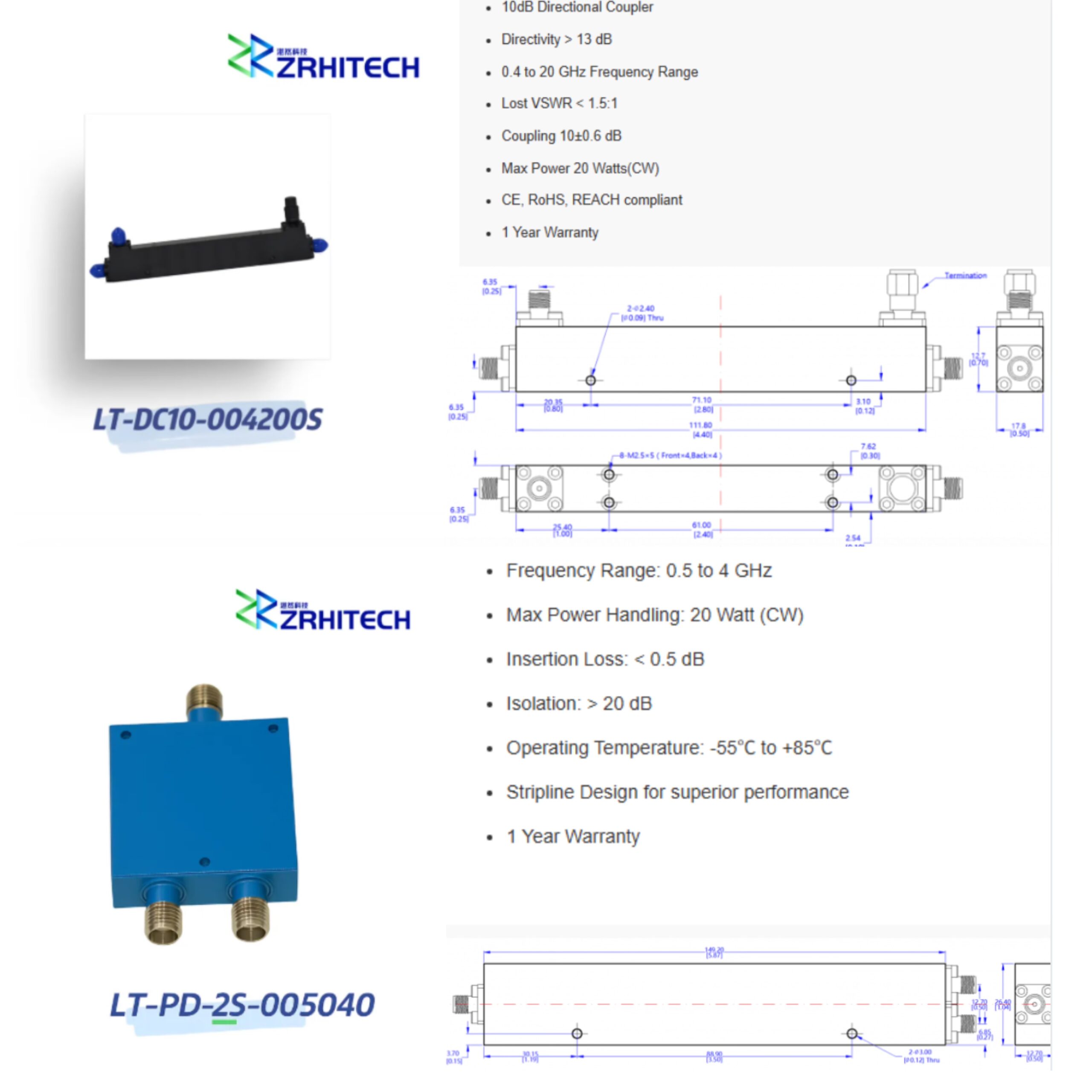
Different Application
Power divider: Used in scenarios where you need multiple ‘equal power signals,’ like multi-antenna arrays at a base station (splitting the signal to 4 antennas), multi-channel transmission in radar systems, or providing the same signal source to multiple devices in RF testing.
Coupler: Used in scenarios where you need to ‘not interfere with the main signal,’ like monitoring transmit power in communication systems (sampling 1% of the signal to measure strength), calibrating RF equipment (using the coupled signal as a reference), or sampling signals without affecting the main link.
Notice
Power dividers and directional couplers both generate power loss during signal transmission, yet the root causes of their loss are entirely distinct. For power dividers, loss stems primarily from equal power distribution. Take a 2-way power divider as an example: it carries a theoretical loss of 3 dB, which means the input signal power is evenly split in half between the two output ports. The fixed theoretical loss can be calculated via a standard formula: theoretical loss = 10 × log(number of output splits).
More output ports bring higher inherent distribution loss, which is an unavoidable feature of equal power division. In contrast, directional couplers produce very little main line loss, generally ranging only from 0.1 dB to 0.5 dB. The vast majority of signal power keeps passing through the main transmission path with slight attenuation. Nearly all power loss associated with the coupler comes from the small portion of signal intentionally diverted to the coupling port for sampling, monitoring or feedback purposes, rather than from evenly splitting the primary signal.
Here are a recommended ZR Hi-tech power divider:
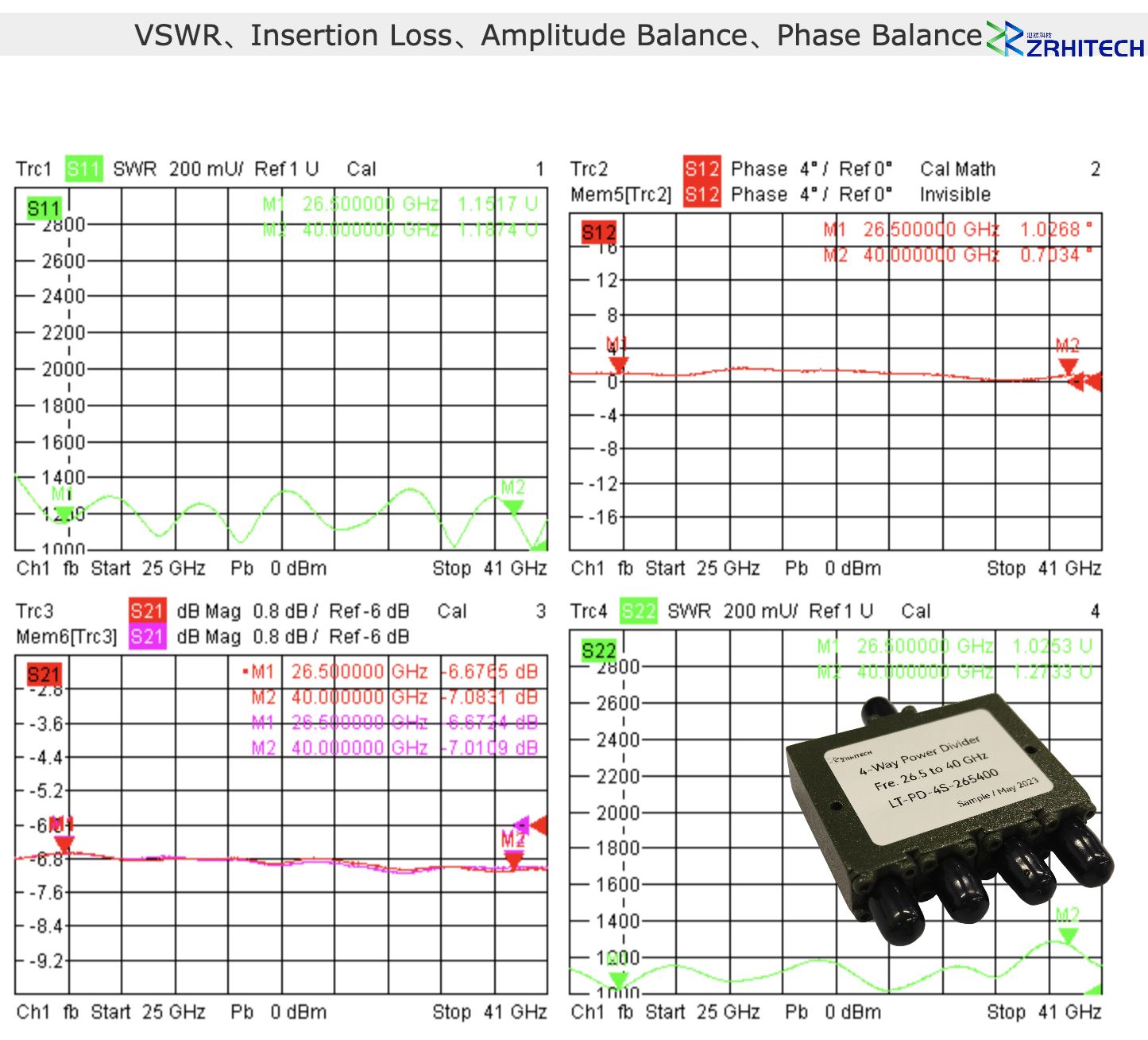
LT-PD-4S-265400
ZR Hi-Tech launches the LT-PD-4S-265400 4-way power divider. It features a sturdy structure and precise production craftsmanship. This model suits scenarios that demand stable RF power distribution. Typical use cases cover Ka-band communication, satellite systems, radar devices, as well as test and measurement instruments.
Key Features:
Frequency Rage: 26.5–40 GHz
Insertion Loss: ≤ 1.6 dB
Isolation: ≥ 16 dB
Amplitude Balance: ≤ 1.5 dB
Peak Power: 1 kW
Conclusion
Simply put, pick a power divider when you need even power distribution. Choose a directional coupler if you only need to extract a small portion of the signal. Both are fundamental RF components. However, they distribute signals in completely different ways. They cannot replace each other in circuit design or practical applications. Learning the differences between power dividers and couplers helps customers select suitable devices for their projects. This also helps optimize the overall performance of RF systems.
If you require high-performance or customized power dividers and directional couplers for communication projects, contact ZR Hi-tech. We provide professional technical support and tailored RF component solutions.



