Newsroom
What Is a Directional Coupler?
A directional coupler is a commonly used RF passive device in radio frequency circuit design. It couples the RF power transmitted in a line to another line. The basic characteristic of a directional coupler is that it only couples the signal in a specified direction.
Overview
A directional coupler is a four-port network:
- Coaxial
- Waveguide
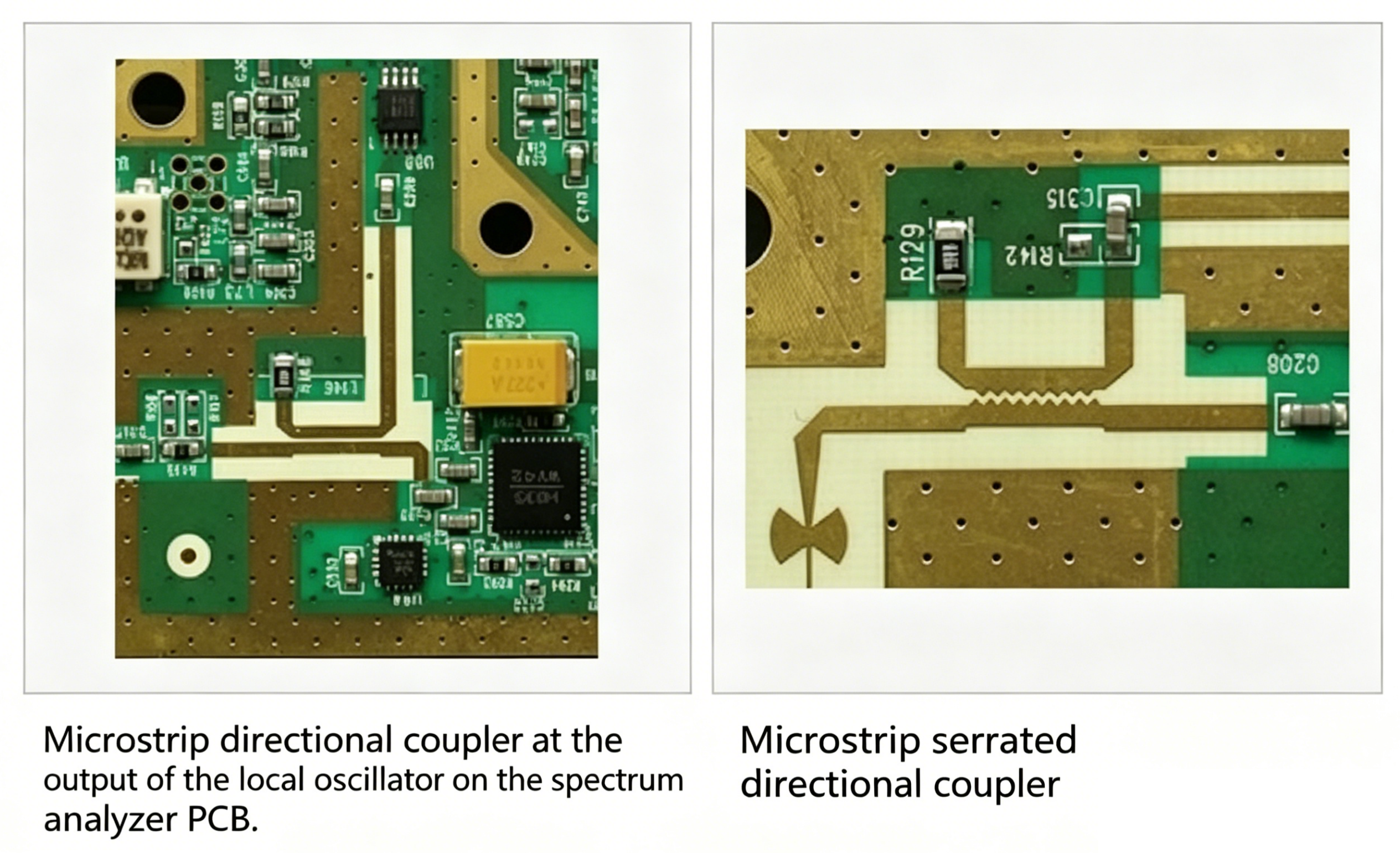
- Microstrip
- Stripline
- Signal sampling for measurement and monitoring
- Signal distribution and combining
- Network analyzers
- Antenna analyzers
- Through‑line power meters
Parameters of the Directional Coupler
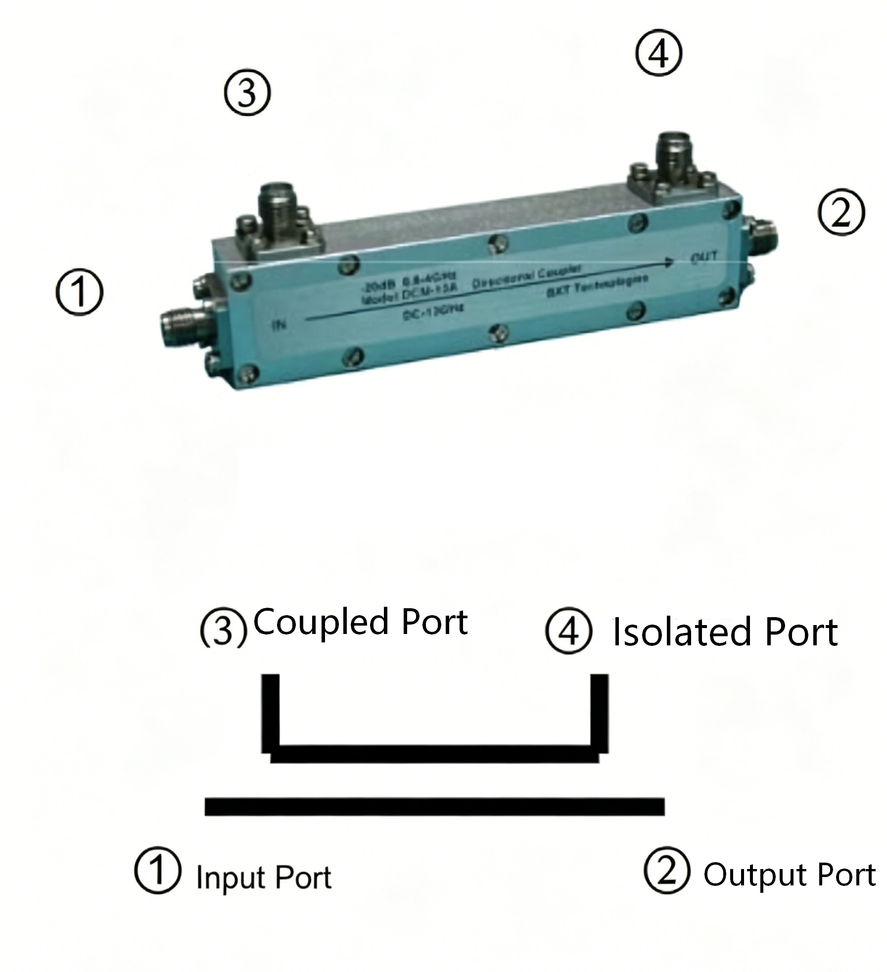
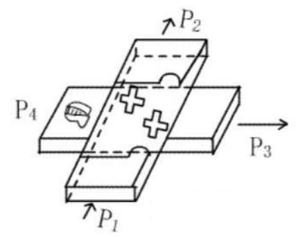
As shown in Figure 1, ideally, when the signal power is input from port 1, the output power should only appear at ports 2 and 3, while port 4 is completely isolated with no power output. However, in practice, some power always leaks to port 4. Let the input power at port 1 be P1, and the output powers at ports 2, 3, and 4 be P2, P3, and P4, respectively. The characteristics of a directional coupler can be described by four indicators: coupling, insertion loss, isolation, and directivity, all measured in dB. Please note that in the following descriptions, all indicators are expressed as positive numbers, whereas in actual applications, negative numbers are used in various calculations.
Coupling Coefficient:
The coupling coefficient represents the ratio of the power input at port 1 that is coupled to port 3, expressed as:
Coupling Coefficient (C) = 10 × log(P1 / P3)
Insertion Loss:
Insertion loss represents the energy loss from port 1 to port 2, expressed as:
Insertion Loss (IL) = 10 × log(P1 / P2)
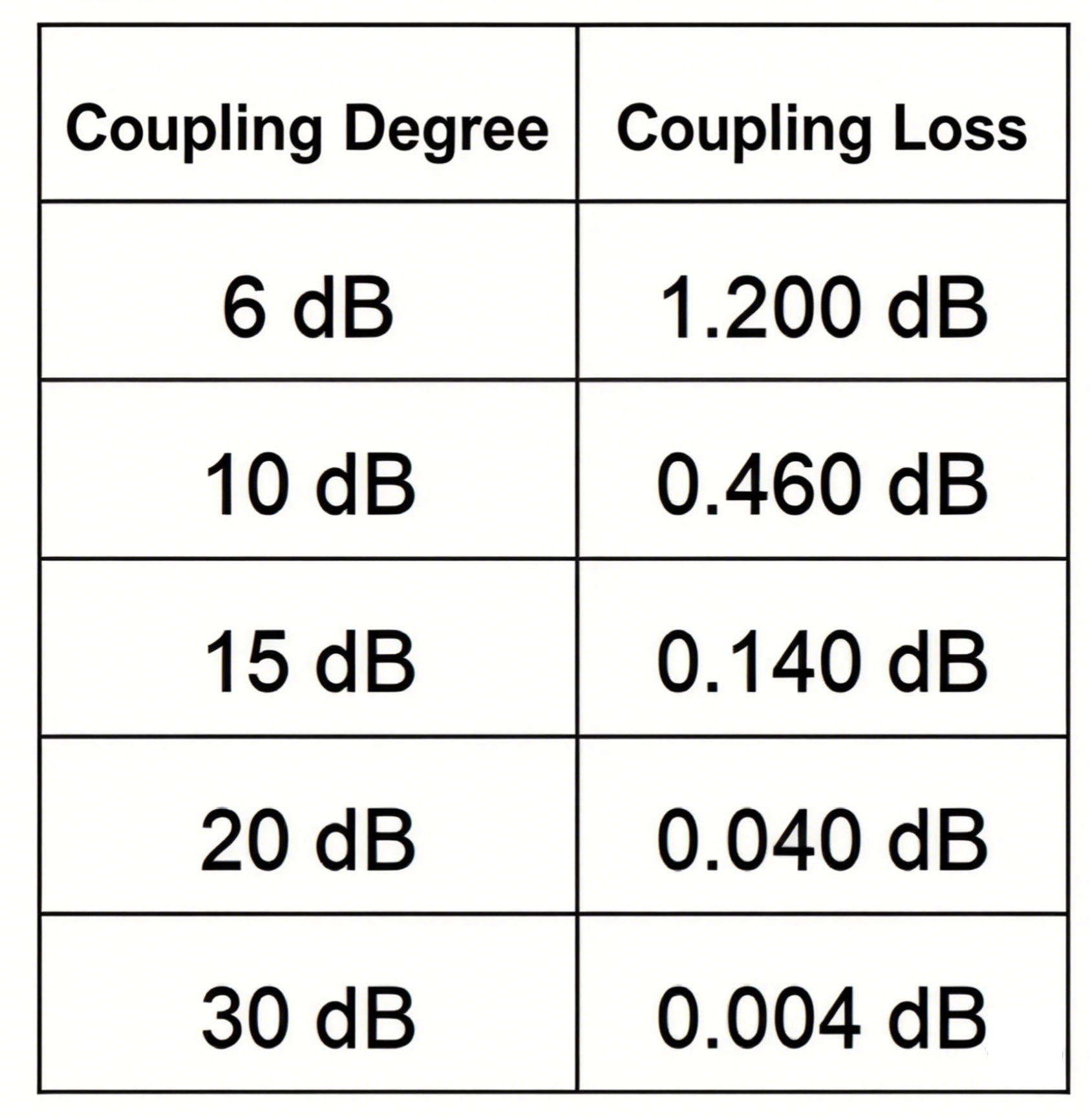
Please note that a portion of the input power at port 1 is coupled to port 3, so the concept of ‘coupling loss’ should be introduced. The table below shows the coupling loss values for various coupling coefficients:
Isolation:
As mentioned earlier, in an ideal directional coupler, port 4 has no power output. However, in reality, some power always leaks from this port. This is the isolation indicator, expressed as:
Isolation (I) = 10 × log(P1 / P4)
Directivity:
Directivity (D) = 10 × log(P3 / P4)
It is particularly important to note that the relationship between coupling, isolation, and directivity is:
Directivity (D) = Isolation (I) – Coupling (C)
Coupling is a design specification, selected according to usage requirements, commonly 6, 10, 20, and 30 dB, so the isolation indicator varies accordingly; directivity, however, is a constant. In most directional coupler specifications, usually only the directivity indicator is listed, and the isolation indicator can be calculated according to the coupling. For example:
Coupling (C) = 30 dB,
Directivity (D) = 25 dB,
then Isolation (I) = 30 + 25 = 55 dB
Several Common Couplers
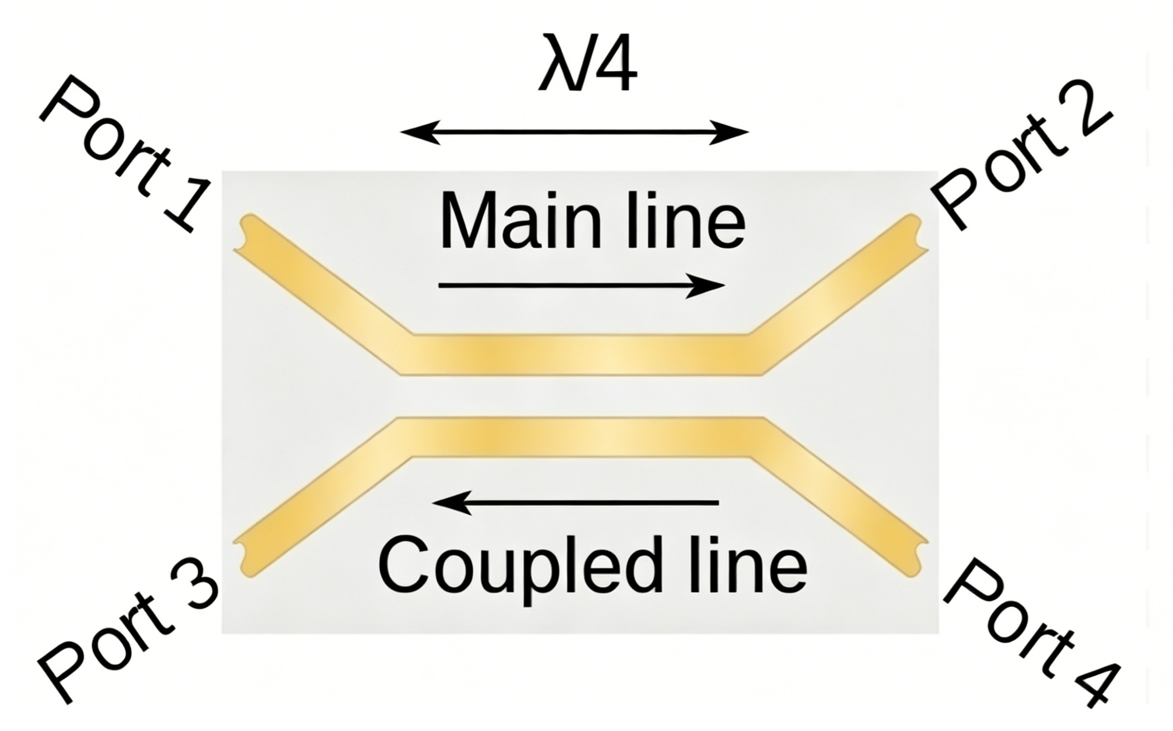
Parallel Line Coupler
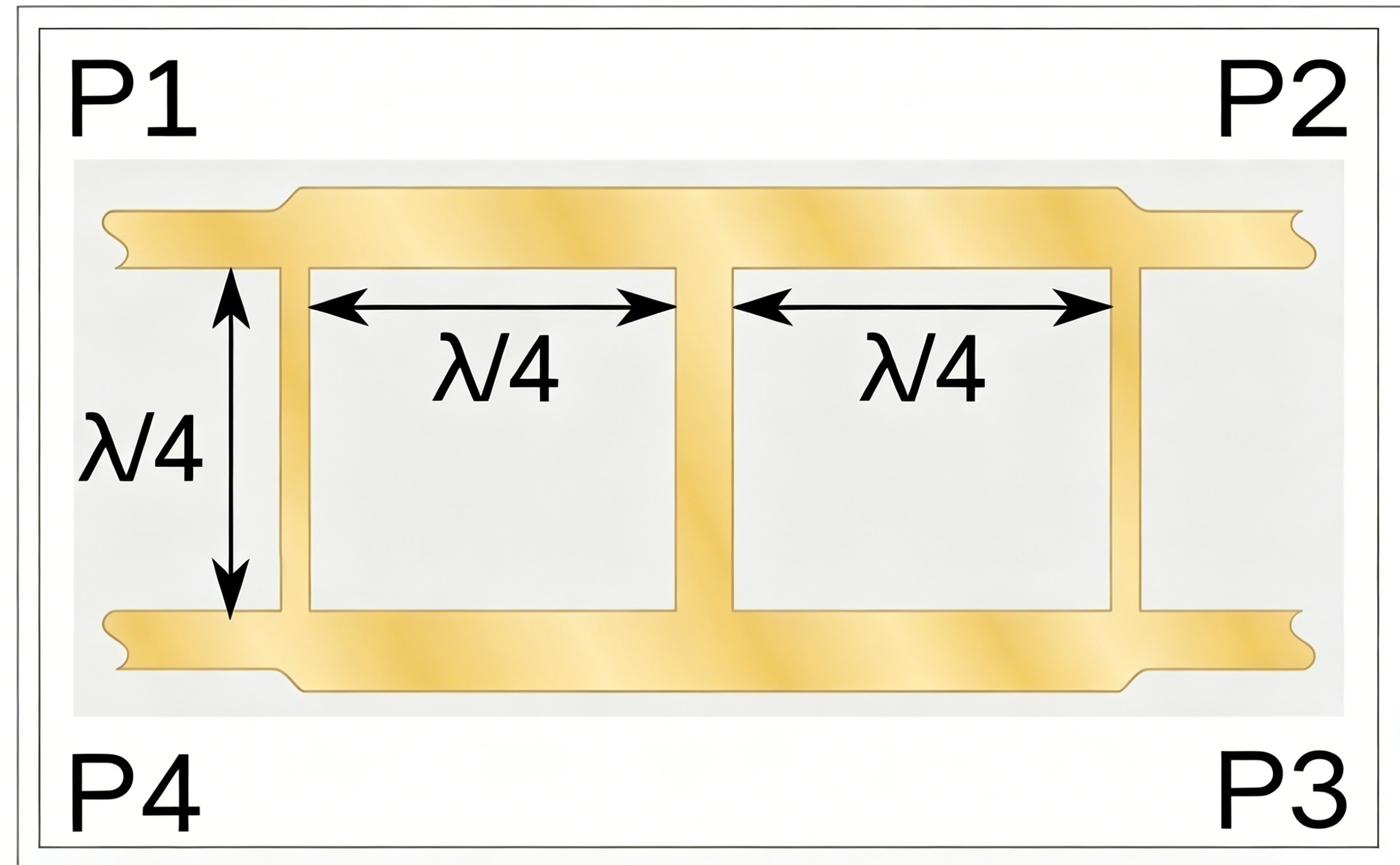
Branch Line Coupler
Waveguide Directional Coupler
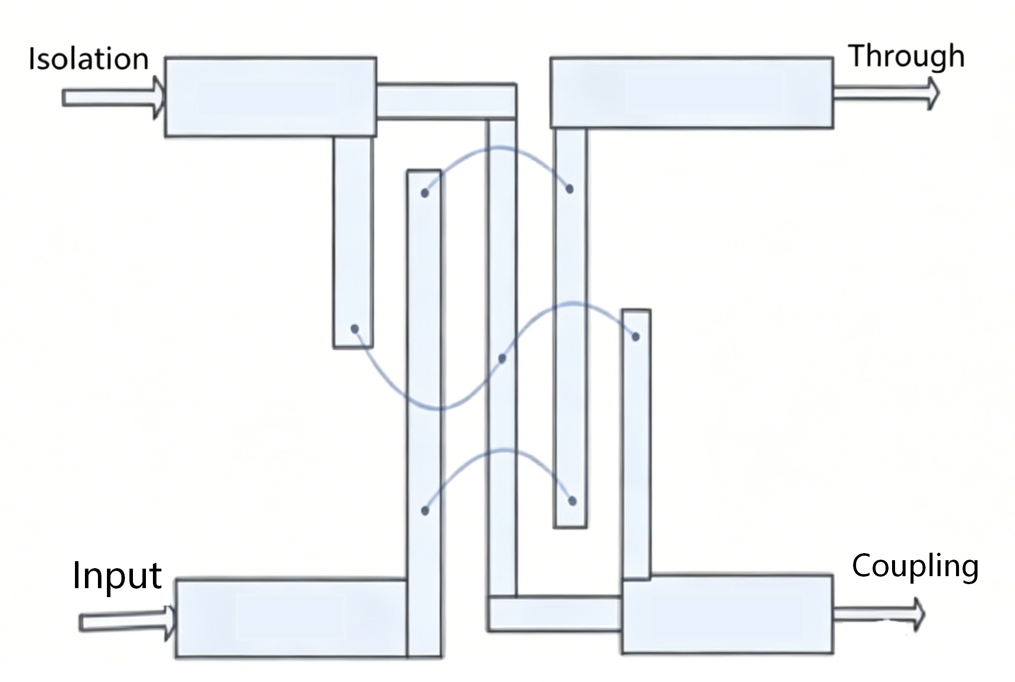
Lange Coupler
Applications of Directional Coupler
Whether in testing and measurement applications or internal system applications, directional couplers are microwave devices with extremely wide applications, as illustrated in the following examples.
Directional coupler used in power combining systems:
In multi-carrier frequency synthesis systems, a 3dB directional coupler (commonly known as a 3dB bridge) is usually used, as shown in the figure.
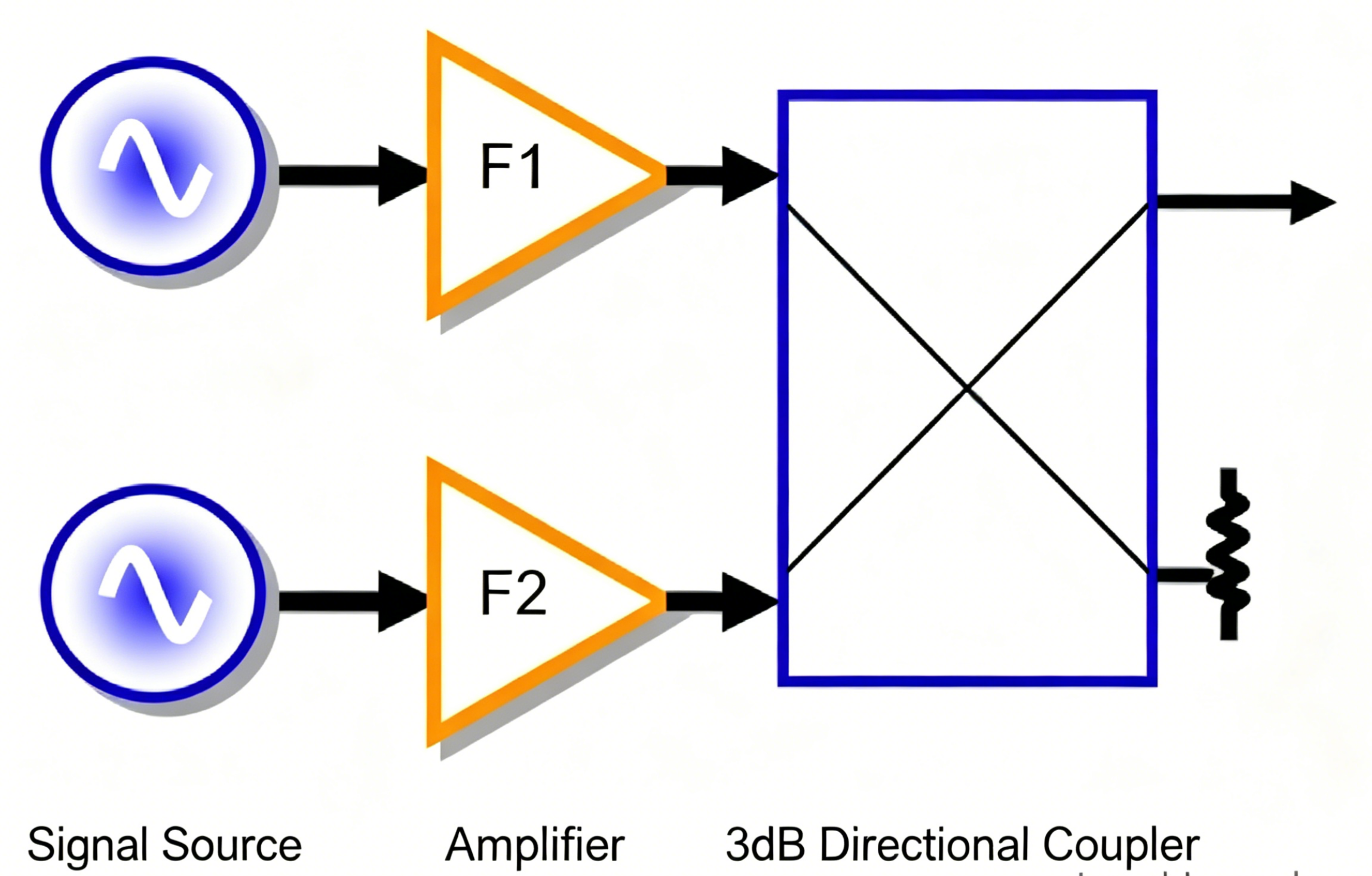
The circuit shown in the figure is commonly found in intermodulation measurement systems and indoor distributed systems with multiple carrier frequencies. In these applications, directional couplers are required to have very high directivity (isolation) to prevent additional intermodulation components between signal sources. To improve isolation, additional devices such as filters or ferrite isolators can also be added. The illustrated 3dB directional coupler (P/N 753345) has a frequency range of 800-2170MHz, a directivity of up to 30dB, which corresponds to an isolation of 33dB.
For signal sampling and monitoring:
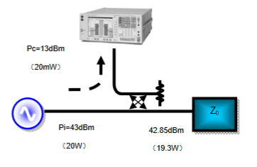
Online measurement and monitoring of transmitters may be one of the most widespread applications of directional couplers. The figure below shows a typical measurement application for a cellular base station. If the transmitter’s output power is 43 dBm (20 W), the coupling factor of the directional coupler is 30 dB, and the insertion loss (line loss plus coupling loss) is 0.15 dB, then a 13 dBm (20 mW) signal is delivered to the base station tester from the coupled port. The through output of the directional coupler is 42.85 dBm (19.3 W), while the power leaked to the isolated port is absorbed by a load.
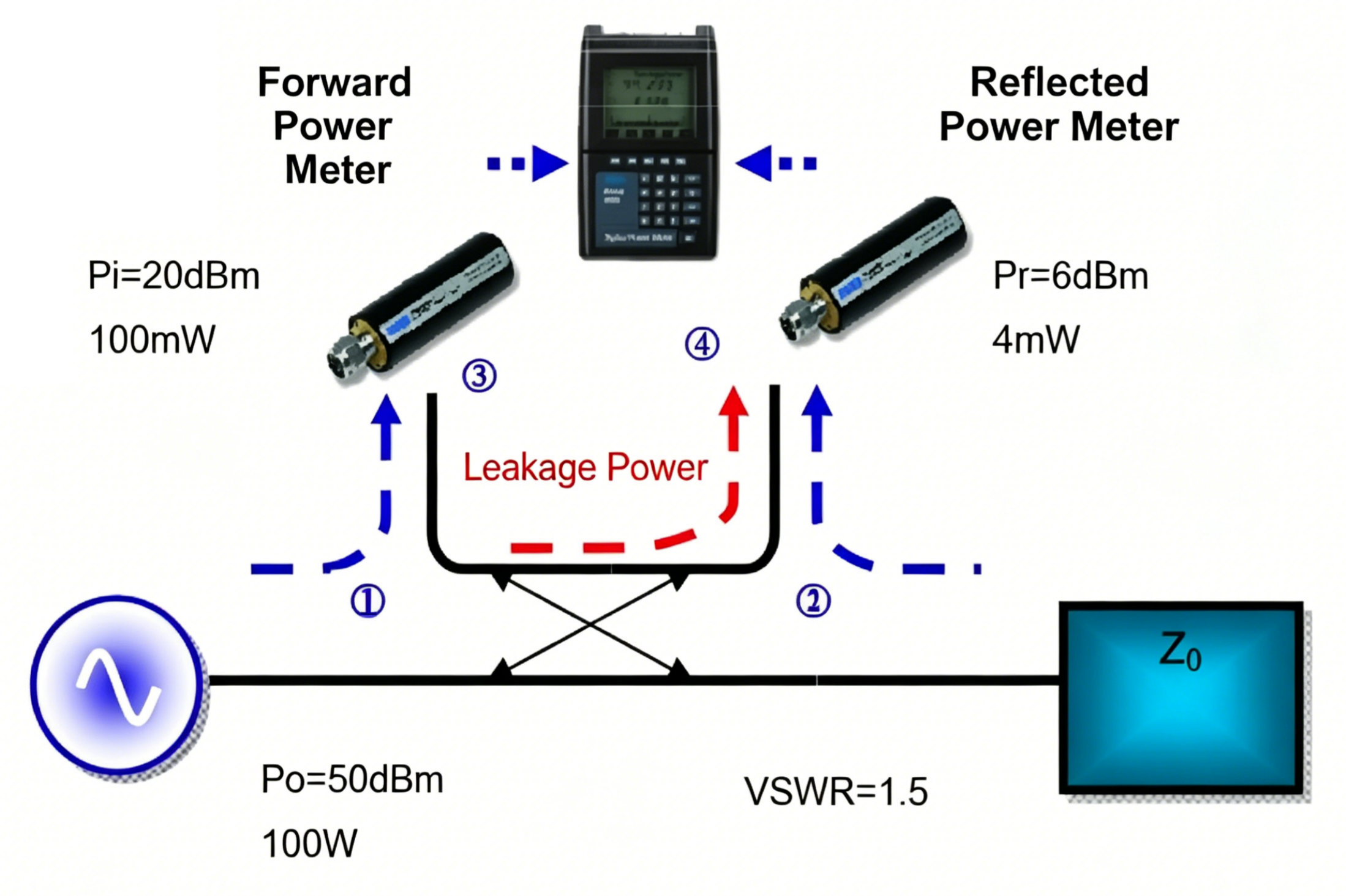
For power and VSWR measurement (reflectometer):
As the core component of a pass-through power meter, the directional coupler can be used for sampling forward and reflected power.
Conclusion
Directional couplers are essential RF passive components used for signal sampling, power monitoring, power combining, and reflected power measurement. Their performance is primarily determined by key parameters such as coupling factor, directivity, isolation, insertion loss, and VSWR.
As modern RF systems continue to demand higher performance and wider bandwidths, selecting the right directional coupler becomes increasingly important for ensuring system efficiency and measurement accuracy.
ZR Hi-Tech offers a wide range of high-performance directional couplers covering various frequency bands, coupling values, and power levels. Whether you need a standard product or a customized RF solution, our engineering team is ready to support your project requirements.
Contact ZR Hi-Tech today to find the ideal directional coupler for your RF application.