
Newsroom
A Complete Guide to Heat Dissipation Methods for RF Power Amplifiers
RF power amplifiers, or RF PAs, act as core components in many devices. Typical scenarios include RF communication systems, radar equipment, base stations and broadcast transmitters. Temperature imposes a huge impact on their performance and service life. RF power amplifiers convert RF signals during operation. A large share of input power turns into waste heat in this process. Insufficient cooling will push up the chip junction temperature directly. This issue triggers multiple adverse outcomes. It may cause gain compression and poor linearity. In severe cases, the power amplifier suffers permanent damage. Data follows the Arrhenius model of thermal aging.
The device failure rate nearly doubles with each 10℃ temperature increase. This fact highlights the necessity of full-range thermal design. Engineers need to carry out thermal optimization from chip to complete system. Such design work is essential to build highly reliable power amplifiers. This article sorts out layered thermal management solutions for RF PAs. It covers packaging design, thermal interface materials, heatsink selection and advanced cooling technologies. It helps RF engineers design high-efficiency heat dissipation schemes for their projects.
Chip-level and Package-level Cooling
The first barrier for heat dissipation starts inside the chip and its packaging, aiming to transfer heat from the junction to the casing with the least thermal resistance.
- Choosing semiconductor materials: Different processes have significant differences in thermal conductivity. Gallium nitride (GaN) has high power density and high thermal conductivity (~130-200 W/mK), making it a top choice for 5G base stations and phased array radars; Gallium arsenide (GaAs) has moderate thermal conductivity, suitable for medium and low power applications; LDMOS (silicon-based) has good thermal conductivity and is cost-effective, so it’s still widely used in broadcasting and communications.
- Chip design and layout: Using parallel arrangements of multi-cell transistors to spread out hotspots; optimizing the drain and gate finger structure to shorten heat diffusion paths and lower channel temperature.
- High thermal conductivity packaging technology: Packaging substrates use aluminum nitride (AlN, thermal conductivity 170–200 W/mK) or beryllium oxide (BeO, thermal conductivity ~250 W/mK, but toxic and regulated), while aluminum oxide (Al₂O₃) is more cost-effective. High-power devices often use metallized packaging (copper-tungsten CuW or copper-molybdenum CuMo carriers) to achieve thermal expansion matching and very low thermal resistance.
- Internal connection optimization: Wire bonding or ribbon bonding can achieve electrical interconnection while also helping with heat dissipation; flip-chip technology mounts the chip directly on the substrate through solder bumps, creating the shortest thermal path and greatly reducing junction-to-case thermal resistance θjc.
Installation Interface Handling
The contact surface between the power amplifier casing and the heatsink is the most likely bottleneck in the heat dissipation chain. Microscopic unevenness creates air gaps (air has a thermal conductivity of only 0.026 W/mK), which seriously block heat flow, so you have to use high-performance thermal interface materials (TIM) and control the mounting pressure.
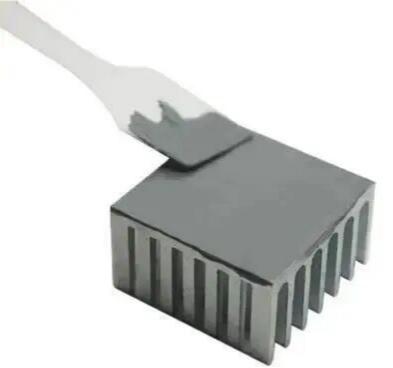
Common thermal interface materials:
- Thermal paste: cheap and easy to fill, but it might dry out and lose performance over long-term high temperatures;
- Thermal pads: pre-shaped and easy to install, with built-in insulation, but relatively higher thermal resistance;
- Phase change materials: soften and fill the interface when heated, with thermal resistance close to thermal paste and more stable;
- Metal foil/indium sheets: indium deforms plastically under pressure, offering very low thermal resistance, suitable for high-power-density GaN amplifiers.
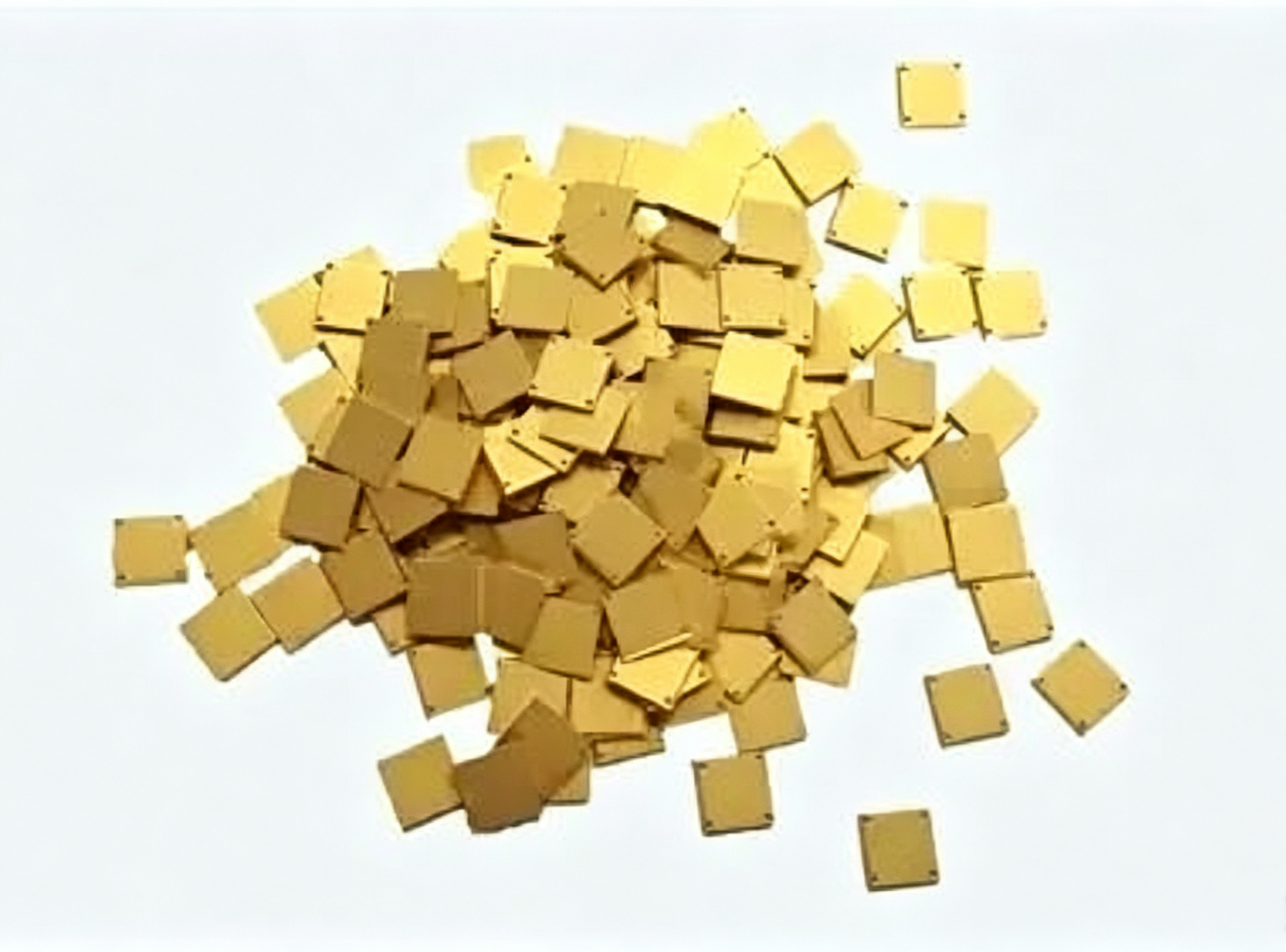
During installation, make sure the contact surfaces are flat and clean, and apply even pressure (recommended screw torque according to the device manual) to ensure the TIM is fully filled and not squeezed out. Proper interface handling can reduce thermal resistance θcs by more than 50%, directly improving the system’s cooling performance.
Heatsink-Level Design
The radiator is responsible for spreading concentrated heat over a larger area and carrying it away through air convection. As for materials, aluminum (6063/6061) is mainstream for finned radiators because it’s lightweight and easy to work with; copper has about 1.8 times the thermal conductivity of aluminum (≈400 W/mK) and is often used for high-thermal-conductivity heatsinks or local inserts.
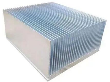
Key design parameters: we can adjust three fin parameters to maximize effective heat dissipation area. These parameters include fin thickness, fin height and fin spacing. The base plate must have sufficient thickness. This design choice lowers the overall thermal resistance of the heatsink. If you adopt forced air cooling, pay attention to fin layout. All fins should be arranged parallel to the airflow direction. Today’s thermal design relies heavily on numerical simulation tools. Engineers use them to optimize airflow turbulence and air pressure loss. This simulation step serves one key goal. It keeps the hottest chip region below the safe junction temperature threshold.
System-level Cooling Method
Based on power levels and environmental requirements, you can choose natural cooling, forced air cooling, liquid cooling, or phase-change cooling to ultimately release heat into the environment.
- 1. Natural cooling (passive heat dissipation): relies on natural air convection and radiation, suitable for low-power situations (<50W), with no noise and high reliability.
- 2. Forced air cooling: uses fans or blowers to enhance convection, and it’s the most common solution for medium to high-power amplifiers (like base stations and broadcast transmitters). You need to balance airflow, air pressure, and noise lifespan. When paired with optimized heat sink fins, it can handle anything from hundreds of watts up to over a thousand watts of heat dissipation.
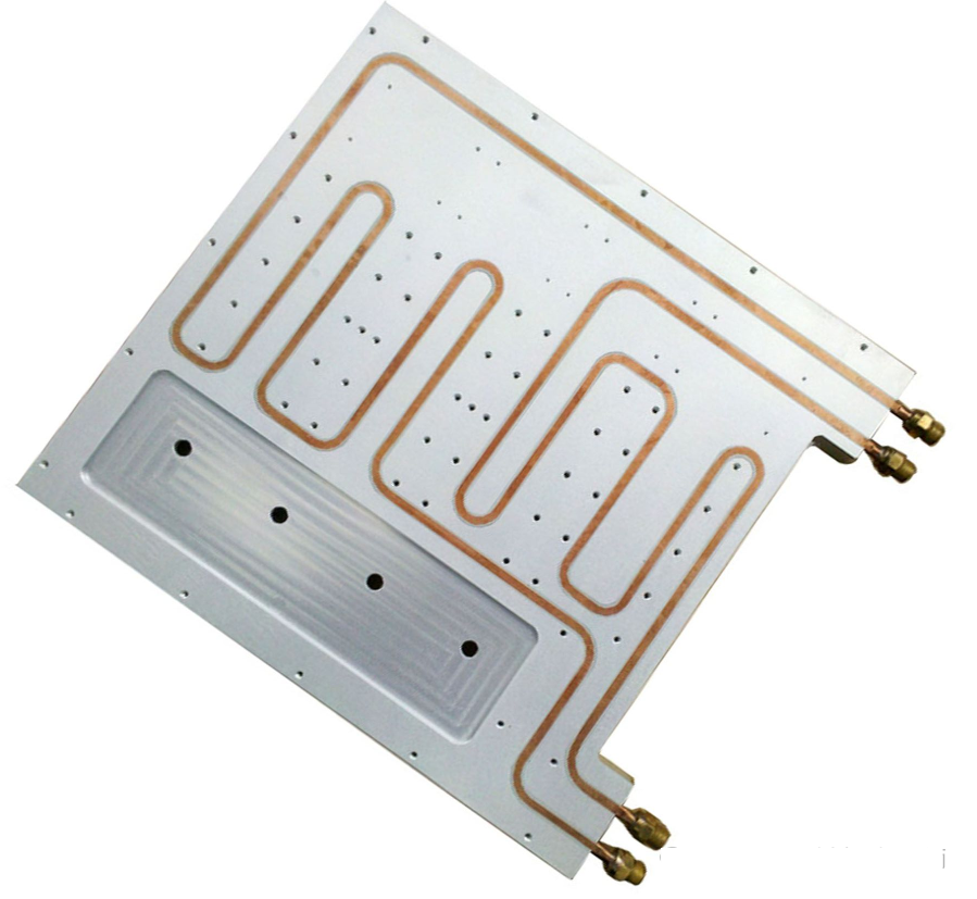
- 3. Liquid Cooling (Cold Plate): By running water or coolant through a cold plate, it can dissipate heat much more effectively than air cooling, making it suitable for high power density phased array radars and high-power amplifier modules (with hot spots over 100 W/cm²). Water cooling systems can transfer heat over longer distances, but they are more complex and have a higher risk of leaks.
- 4. Phase-change cooling and heat pipes/heat spreaders: Heat pipes use the working fluid’s evaporation-condensation cycle to quickly transfer heat, with an effective thermal conductivity of up to several thousand W/mK. They’re often embedded in radiators as ‘superconducting’ components to get rid of local hotspots. Spray cooling and microchannel cooling are used for extreme heat flux scenarios, like in aerospace or high-power lasers.
Thermal Design and Simulation Verification
Modern RF power amplifier design relies heavily on advanced thermal simulation and testing loops. Engineers use thermal resistance network analysis to calculate the total thermal resistance from junction to ambient θja = θjc + θcs + θsa, and during the prototype stage, they use CFD software like FloTHERM or Icepak to simulate airflow and temperature distribution, optimizing heatsink geometry, fan selection, and airflow paths ahead of time. In addition, infrared thermal imaging and thermocouple measurements can verify hotspot temperatures against simulations, ensuring the product meets long-term reliability.
Comparison and Selection Strategy of Mainstream Cooling Methods
For different RF power amplifier scenarios, the table below summarizes the characteristics of cooling methods to help engineers make quick decisions.
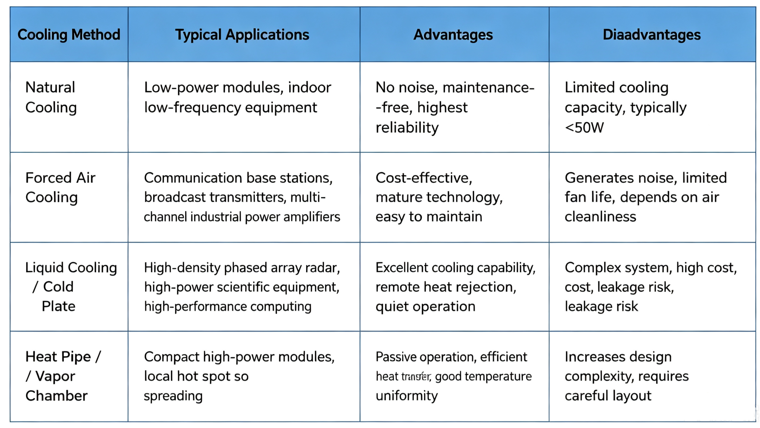
In addition, in real engineering, ‘hybrid cooling’ is often used: for example, high-power GaN amplifiers combined with water-cooled plates and equalization plates, or air-cooled radiators with embedded heat pipes. For high reliability requirements (like in aerospace), redundant design and strict thermal cycling testing are needed.
Key Points of Thermal Management Engineering Practice
- Junction temperature control goal: Usually requires junction temperature Tj ≤ 125℃ (silicon LDMOS) or ≤ 200℃ (GaN), and it’s recommended to keep Tj 15~20℃ below the rated value for safety margin.
- Thermal resistance measurement and monitoring: You can use transient thermal testing (T3Ster) to extract structure functions and locate internal packaging defects.
- Long-term reliability: Heat dissipation design should also consider matching the coefficient of thermal expansion (CTE) to avoid solder fatigue cracking. Phase-change interface materials adapt better to cyclic thermal stress.
- Environmental adaptability: Outdoor base stations need dust and water protection; forced air cooling should add washable dust filters; liquid cooling systems need corrosion inhibitors and antifreeze.
Conclusion
Cooling design for RF power amplifiers is not an optional upgrade anymore. It acts as a decisive factor for three core indicators. These indicators are system performance, power efficiency and component service life. Thermal optimization covers the whole product chain. It ranges from GaN chip packaging to complete liquid cold plate systems. All structural sections require low thermal resistance design. This work also demands cross-disciplinary technical cooperation. Two mainstream applications keep boosting integration levels. They are 5G Massive MIMO and phased array radar. Advanced cooling methods support higher power density RF frontends. Typical solutions include embedded microchannels and jet impingement cooling. RF engineers can maintain technical competitiveness in two practical ways. First, they make full use of thermal simulation software. Second, they select the most suitable heat dissipation scheme for their design.
If you need high-performance RF components, customized test fixtures or professional thermal design consultation for your power amplifier projects, contact ZR Hi-tech. Our engineering team provides full-cycle RF solutions tailored for communication base stations, military radar and industrial transmitters, helping you build thermally stable, long-lasting RF systems.



