Newsroom
Power Divider: All Things You Want to Know About It
Power dividers are a common component in radio frequency (RF) systems. They distribute signals proportionally across multiple branches, acting as both “one-to-many” and “power distribution.”
The reverse of power divider is power combiner. Clearly, the function of a power combiner is to combine energy from multiple sources, thus playing a crucial role in wireless communication, radar, and test and measurement.
In this article, we will focus on power dividers, explaining their working principles, functions, classifications, and technical specifications.
What is a Power Divider? General Overview
A power divider is a device that splits the energy of a single input signal into two or more outputs of equal or unequal energy. Conversely, it can combine the energy of multiple signals into a single output, in which case it can also be called a combiner. A certain degree of isolation must be maintained between the output ports of a power divider.
Power dividers are typically classified by output type, such as 1-to-2 (one input, two outputs) or 1-to-3 (one input, three outputs). The main technical parameters of a power divider include power loss, voltage standing wave ratio (VSWR) of each port, and isolation between the power distribution ports.
In simpler terms, when the RF input power is too high, the next stage device cannot handle the excessive power. Therefore, the RF input power is evenly or unevenly distributed to several ports. If necessary, the energy distributed to each port is then combined (power combiner). High-power RF devices are relatively expensive, and power dividers undoubtedly help reduce costs.
What is the Purpose of a Power Divider?
A power divider’s function is to equally split a single input satellite intermediate frequency (IF) signal into several output channels, typically a two-way divider, a four-way divider, a six-way divider, etc. Power dividers operate at frequencies between 950MHz and 2150MHz, and most people are familiar with them. The three devices mentioned above have completely different uses and performance characteristics, but their names are often confused in daily use, causing confusion.
In a satellite television receiving system, multiple satellite receivers share one antenna, several antennas share one satellite receiver, or two or more satellite receivers share two or more antennas. The connections between them, besides relying on cables, are mainly achieved through the combination and programming of switchers.
A power divider is used to connect multiple satellite receivers. If one antenna needs to connect multiple satellite receivers, a power divider is required. The choice of power divider depends on the number of receivers connected. For two receivers, a two-way power divider is used; for four receivers, a four-way power divider is used.
What is Another Name for a Power Divider?
Power dividers, also called overcurrent dividers, come in active and passive types. They can distribute one signal into several outputs. Generally, each output has a few dB of attenuation. The attenuation varies depending on the signal frequency and the type of divider. To compensate for the attenuation, an amplifier is added to create a passive power divider.
What are the Different Types of Power Dividers?
Power dividers come in various types and can be classified according to different standards. Below are some classification methods and specific types for different application scenarios:
1. Microstrip Power Dividers
Microstrip power dividers are fabricated on a dielectric substrate using printed circuit board technology. They offer significant advantages such as flexible design, low cost, small size, and easy integration. Their performance is significantly affected by the substrate material, process precision, and operating frequency.
As the number of power dividers increases, the design challenges increase dramatically. Multi-level tree-like cascaded structures are typically required, leading to increased accumulated losses, difficulty in phase consistency control, complex overall layout, and complex isolation resistor network design, among other technical challenges. Therefore, high-number microstrip power dividers are an important indicator of design capability and process technology level.
2. Resistor Power Dividers
Resistor power dividers are broadband devices composed entirely of resistor networks. Their greatest characteristic is their ability to operate stably from DC to extremely high frequencies. Power distribution and impedance matching at each port are achieved through precise resistor value matching.
Its disadvantages include the lack of isolation between output ports; load changes at any port directly affect other ports, and its insertion loss is much greater than the theoretical distribution loss because some signal energy is dissipated as heat in the resistors, limiting its power capacity. It is well-suited for test and measurement scenarios with extremely high bandwidth and amplitude consistency requirements but low isolation requirements.
3. Cavity Power Divider
A cavity power divider seals the circuit structure inside a metal cavity, operating using cavity resonance and distributed parameters. This structure gives it significant advantages such as high power capacity, low insertion loss, high quality factor, and stable and reliable performance.
Its main disadvantages are its relatively large size and weight, and higher manufacturing cost. It is primarily used in scenarios with stringent power and efficiency requirements, such as macro base stations and high-power indoor distributed systems.
4. Waveguide Power Divider
A waveguide power divider uses a metal waveguide as the transmission medium and is the preferred solution for high-frequency bands such as millimeter waves. Its working principle is based on various excitation and distribution structures of electromagnetic waves within the waveguide. Waveguide structures inherently possess extremely low transmission loss and extremely high power handling capabilities.
However, their disadvantages are equally apparent, including their very large size, complex manufacturing process, and high cost, typically limiting them to high-end applications such as satellite communications, high-power radar, and scientific instruments.
Typical Application Scenarios of Power Dividers
Power dividers are used in all aspects of modern radio frequency (RF) systems.
In wireless communication, they are core components of indoor distribution systems, responsible for uniformly distributing base station signals to all antenna points within a target area.
In advanced radar systems, especially phased array radars, power dividers, together with phase shifters, form complex antenna feed networks, providing precise amplitude and phase excitation to thousands of radiating elements.
In RF test and measurement, power dividers are used to synchronously feed a single signal source to multiple test instruments for parallel comparison and collaborative analysis.
Furthermore, in satellite communication and navigation receiving systems, they are also used to distribute signals from a single antenna to multiple receiving devices.
How do Power Dividers Work? The Principle of Power Divider
To understand the working principle of a power divider, it’s necessary to understand its technical specifications. Here, we will explain both aspects.
1. The Principle of a Power Divider
The working principle of a power divider is based on the transmission and transformation characteristics of electromagnetic waves in a circuit structure. Its performance is precisely characterized by a series of scattering parameters. When an RF signal is input, the power is redistributed internally through a specific transmission line structure and impedance matching network.
Taking the classic Wilkinson power divider as an example, its core is to use a quarter-wavelength transmission line to complete impedance transformation, achieving uniform power distribution. It also uses integrated resistors to provide a dissipation path for reverse signals between output ports, thus achieving high isolation.
2. Technical Specifications of a Power Divider
The technical specifications of a power divider include frequency range, power handling capacity, distribution loss from main path to branch path, insertion loss between input and output, isolation between branch ports, and voltage standing wave ratio (VSWR) of each port. To judge the performance of a power divider, we need to focus on the following six core indicators:
Frequency Range
This is a prerequisite for the operation of various RF/microwave circuits. The design structure of a power divider is closely related to its operating frequency. The operating frequency of the power divider must be determined first before proceeding with the design.
Power Handling Capacity
In high-power dividers/synthesizers, the maximum power that circuit components can handle is a core indicator, determining the type of transmission line used to achieve the design objectives. Generally, the power handling capacity of transmission lines, from lowest to highest, is: microstrip line, stripline, coaxial line, air stripline, and air coaxial line. The choice of transmission type depends on the design requirements.
Distribution Loss
The distribution loss from the main path to the branch path is essentially related to the power distribution ratio of the power divider. For example, the distribution loss of a two-way power divider is 3dB, while that of a four-way power divider is 6dB.
Insertion Loss
Insertion loss between input and output is caused by factors such as imperfections in the medium or conductor of the transmission line (e.g., microstrip line). It determines the degree of power attenuation as the signal passes through the device and is a key indicator affecting system energy efficiency. The loss due to the input VSWR also needs to be considered during the design process.
Isolation
Isolation between tributary ports is another important indicator of a power divider, reflecting the degree of mutual interference between output ports. Higher isolation results in better system stability. Sufficient isolation is required so that power input from each tributary port can only be output from the main port and not from other branches.
VSWR
A lower VSWR for each port is better. Power dividers are commonly used to connect multiple satellite receivers, dividing a single input satellite intermediate frequency signal into several outputs. Common configurations include two-way, four-way, and six-way power dividers. The choice of power divider depends on the number of receivers connected. For example, a two-way power divider is used for two receivers, and a four-way power divider is used for four receivers.
About ZR Hi-Tech: Leading Power Divider Manufacturer
ZR Hi-Tech is a company specializing in integrated circuit manufacturing, committed to providing customers with high-performance, high-reliability integrated circuit solutions. Our team consists of experienced professionals.
If you are looking for a reliable power divider manufacturer solution for your project, please consult with ZR Hi-Tech experts!
thousand grade and ten thousand grade Purification workshops
ZR Hi-Tech’s Product Advantages and Core Capabilities
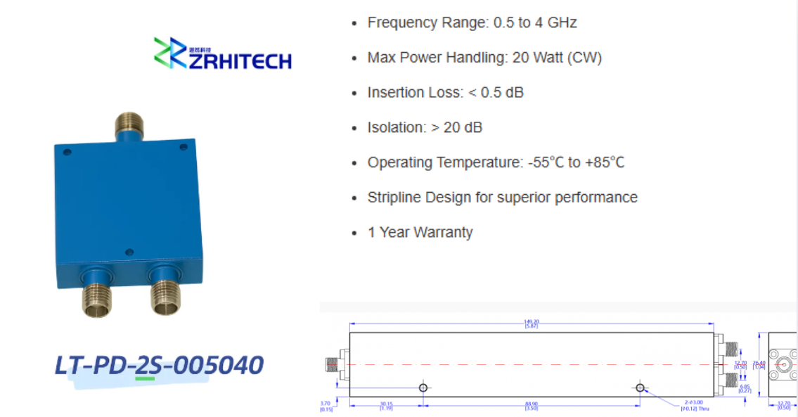
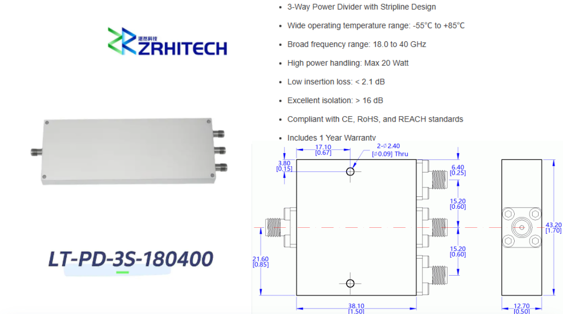
With deep technological expertise, we have built a comprehensive product portfolio of high-performance power dividers, dedicated to providing professional solutions for our customers.
Power Divider Product Portfolio: Our microstrip power divider series employs advanced electromagnetic simulation and high-precision manufacturing processes to ensure consistent and superior performance across our entire product line, from low to high power divider counts. Our resistive power divider series utilizes high-precision thin-film resistors, guaranteeing amplitude and phase stability over an ultra-wide bandwidth.
High Reliability Assurance: Our entire power divider product line adheres to stringent quality standards, undergoes comprehensive environmental stress screening and reliability testing, and complies with CE, RoHS, and REACH standards.
Deep Customization Services: We possess strong custom development capabilities and can provide flexible customization services based on specific customer needs, including operating frequency band, power divider count, interface type, and mechanical structure. For customized specifications or special requirements, please contact us directly.