
Newsroom
Power Divider Test Measurement Methods: Complete Guide for RF Engineers
A power divider is a passive RF component. It divides one input signal into two or more output signals with equal or unequal power levels. Based on the reciprocity theorem, a power divider can operate in both forward and reverse directions. In the forward direction, it distributes RF power to multiple outputs. In the reverse direction, it combines multiple signals into a single output. In this case, it is also called a power combiner. Power dividers are widely used in wireless communication, radar systems, satellite communications, and RF test equipment. To ensure stable RF performance, accurate testing and measurement of parameters such as insertion loss, VSWR, isolation, and phase balance are critical. This article introduces common RF power divider test measurement methods and key performance parameters in microwave systems.
Principle of the Power Divider
The working principle of a power divider is based on transmission line structures and impedance matching networks. It distributes the input RF power to multiple output ports according to a specific power ratio.
For example, the widely used Wilkinson power divider uses quarter-wavelength transmission lines to achieve impedance transformation. At the same time, isolation resistors between the output ports help absorb reverse signals and reduce interference between channels. This design enables the power divider to achieve low insertion loss, good impedance matching, and high isolation performance in RF and microwave systems.
Main Types of Power Divider
1. Wilkinson Power Divider
2. Resistive Power Divider
3. Microstrip Power Divider
4. Cavity Power Divider
5. Waveguide Power Divider
6. T-Junction Power Divider
Key Technical Indicators for Power Divider Testing
1. Insertion Loss:
The power attenuation when the signal passes through the power divider, including two parts:
- Theoretical distribution loss: Determined by the power split ratio, e.g., 3 dB for 2-way, 6 dB for 4-way
- Additional loss: Caused by conductor and dielectric losses
An ideal Wilkinson power divider has only theoretical distribution loss, while practical devices have additional loss. When selecting, products with low insertion loss should be chosen.
2. Voltage Standing Wave Ratio (VSWR) / Return Loss:
Characterizes the quality of port impedance matching. The closer the VSWR is to 1, the better, indicating smaller reflection and higher energy transmission efficiency. Generally required VSWR ≤ 1.3 (all ports).
3. Isolation:
The ability of output ports to be isolated from each other, meaning a signal entering port 2 will not output from port 3. Higher isolation means less interference between ports. Wilkinson power dividers achieve high isolation through isolation resistors, with typical values >20 dB.
4. Amplitude Balance:
The uniformity of power distribution among output ports, usually required to be ≤ 0.3 dB.
5. Phase Balance:
The phase error between output ports, crucial for coherent systems such as phased arrays and power combining, usually required to be <3°.
6. Delay Error:
Refers to the differences in signal transmission time among output ports. In wideband systems, phased array radars, and high-speed digital communications, delay consistency directly affects signal coherence and system performance. Delay error is usually related to inconsistencies in transmission line lengths or substrate dielectric constant. For Wilkinson power dividers, theoretically, all branch transmission lines are equal in length (all λ/4), so delays should be consistent, but manufacturing errors can cause actual delay deviations.
7. Other Key Indicators:
- Frequency Range: Operating band, performance deteriorates outside this range
- Power Handling: Maximum operating power without long-term damage
- In-Band Flatness: Range of insertion loss fluctuations within the frequency band
Measurement Methods of Power Divider
1. Insertion Loss Measurement
Using a Vector Network Analyzer (VNA) to measure S-parameters:
- Measure S21 (transmission coefficient from input to output)
- Actual insertion loss = |S21| (dB) – theoretical allocation loss (dB)
2. VSWR / Return Loss Measurement
- Measure S11 (reflection coefficient at the input port)
- Return loss = -20·log|S11| (dB)
- VSWR = (1 + |S11|)/(1 – |S11|)
3. Isolation Measurement
- Measure S23 (e.g., transmission coefficient from port 2 to port 3) between output ports
- Isolation = -20·log|S23| (dB)
4. Amplitude / Phase Balance Measurement
- Set the VNA to multi-port mode, measuring S21, S31, etc. for each output port simultaneously
- Amplitude imbalance = max|S21| – min|S21| (dB)
- Phase imbalance = max∠S21 – min∠S21 (degrees)
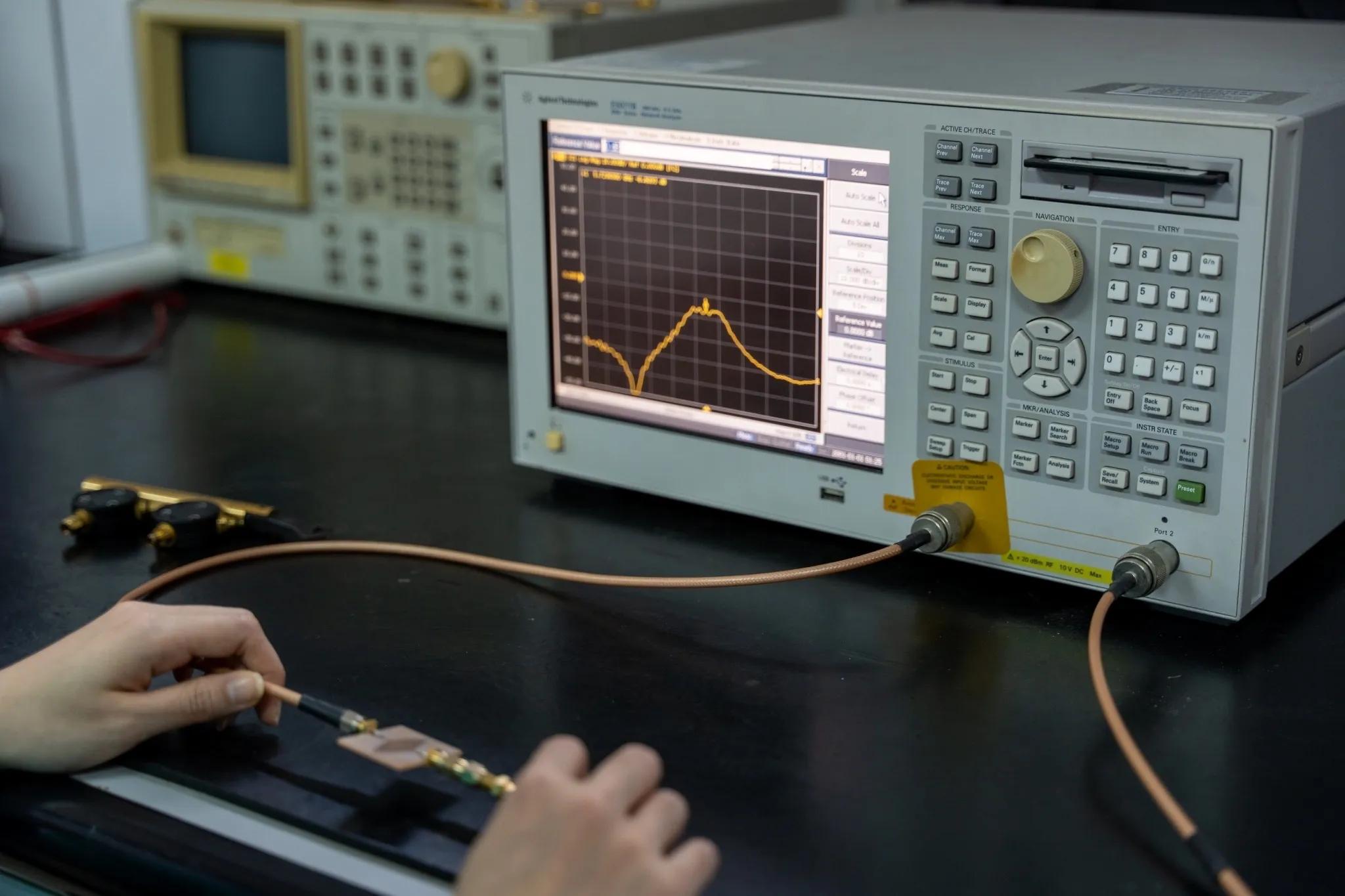
5. Delay Error Measurement
- Time-domain method: Use the VNA’s time-domain transform function (TDR) to directly measure the group delay of each port
- Frequency-domain method: Measure the phase response and calculate group delay using τ = -dφ/dω
- Delay error = maximum difference of group delays among all ports
Selection Guide and Steps
1. Determine the frequency range
- Ensure the power divider covers the system operating frequency band
- Note: Wilkinson type is usually limited to a few hundred MHz at low frequencies, while resistive type can start from DC
2. Determine the number of ports
- Common: 2-way, 3-way, 4-way, 8-way, 16-way, 32-way, 64-way
- For a high number of ports (>4), multi-stage tree cascading is usually used; pay attention to cumulative loss
3. Evaluate power handling
- Average power vs peak power
- Reserve at least 20% margin
4. Check key specifications
- Insertion loss: the lower the better (additional loss usually <0.5 dB is preferred)
- Isolation: >20 dB (general scenarios), >40 dB (high-demand scenarios)
- VSWR: ≤1.3 (all ports)
- Amplitude/phase balance: choose according to system coherence requirements
5. Connectors and impedance
- Common: SMA (≤18 GHz), N-type (≤11 GHz), 2.92mm/2.4mm/1.85mm (millimeter wave)
- Impedance: 50Ω (RF) or 75Ω (cable TV)
Conclusion
A power divider is an essential passive RF component used to distribute a single RF signal into multiple output paths with a specific power ratio. It can also operate in reverse as a power combiner. In practical RF and microwave systems, the performance of a power divider mainly depends on key parameters such as insertion loss, isolation, VSWR, amplitude balance, and phase consistency.
Accurate testing and measurement are critical to ensuring stable signal transmission and reliable system performance. As RF technologies continue to develop toward higher frequencies and wider bandwidths, high-performance power divider solutions and precise measurement methods become increasingly important in wireless communications, radar, satellite systems, and test equipment.
With over 20 years of experience in RF and microwave component design, ZR Hi-Tech provides reliable power divider solutions with excellent electrical performance and OEM/ODM customization support. If you are looking for professional RF components or customized microwave solutions, feel free to contact ZR Hi-Tech for more information.



