
Newsroom
Must-Know for RF Engineers: Waveguide Directional Couplers – Principles, Types & Design Guide
In our previous articles, we explored two widely used directional coupler designs: the branch-line directional coupler and the parallel coupled-line directional coupler. Both designs are based on transmission line theory. They are widely used in RF and microwave circuits for signal coupling, power monitoring, and signal distribution.
However, transmission lines are not the only solution for building directional couplers. In high-frequency applications, especially at microwave and millimeter-wave frequencies, waveguide structures provide another effective approach. They offer advantages such as low insertion loss, high power handling capability, and excellent RF performance.
So, can waveguides also be used to make directional couplers? The answer is yes. In this article, we will explore rectangular waveguide directional couplers. We will discuss their working principles, structural features, key performance parameters, and typical applications in RF and microwave systems.
The rectangular waveguide directional coupler, like the two directional couplers introduced above, is made up of a main waveguide and a secondary waveguide. Coupling happens through coupling holes on the common wall between the main and secondary waveguides. Depending on the number and shape of these holes, waveguide directional couplers can be classified into single-hole couplers, multi-hole couplers, cross-hole couplers, as well as other structures like the double-T matching and waveguide slot bridges.
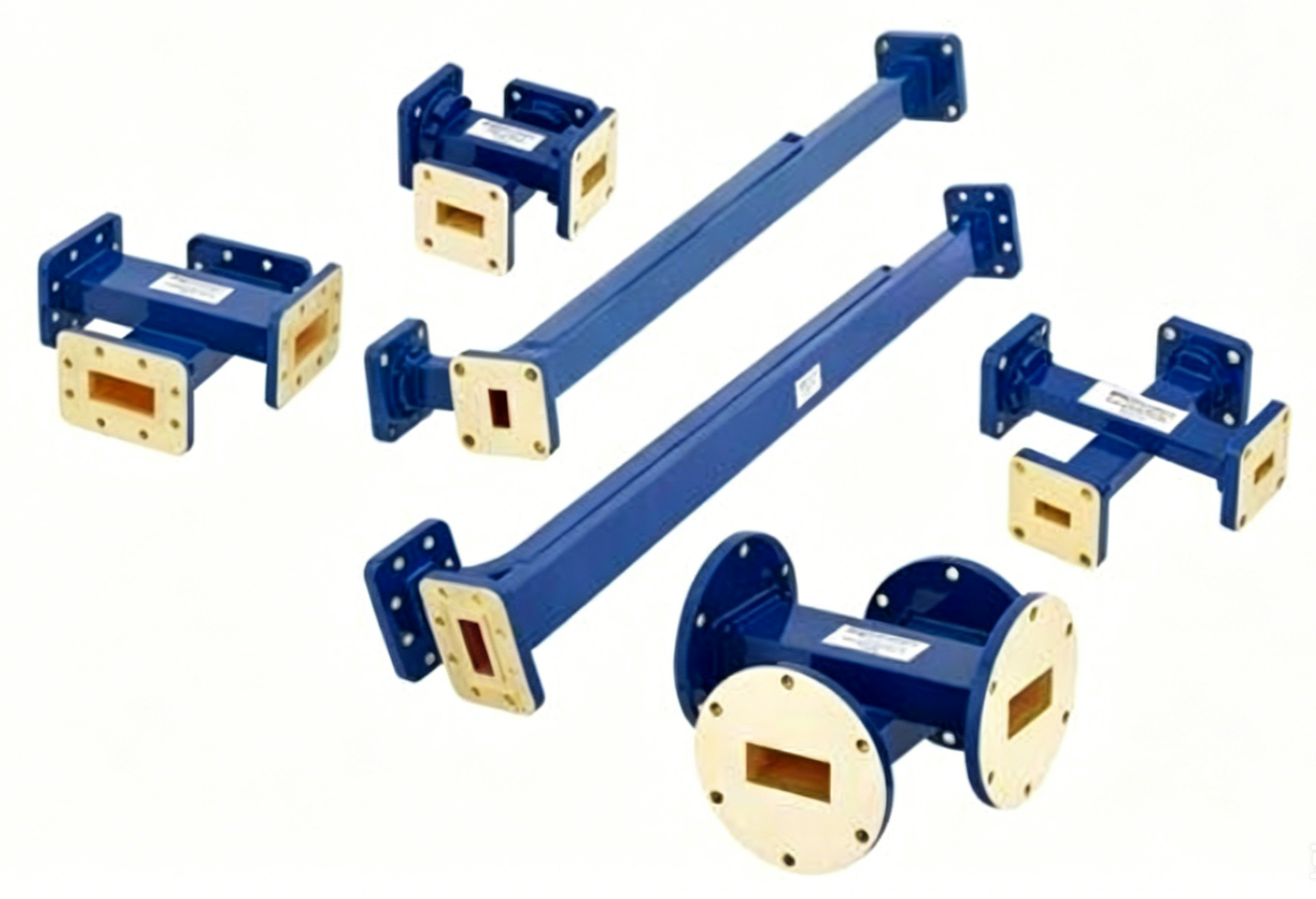
Single-port Directional Coupler
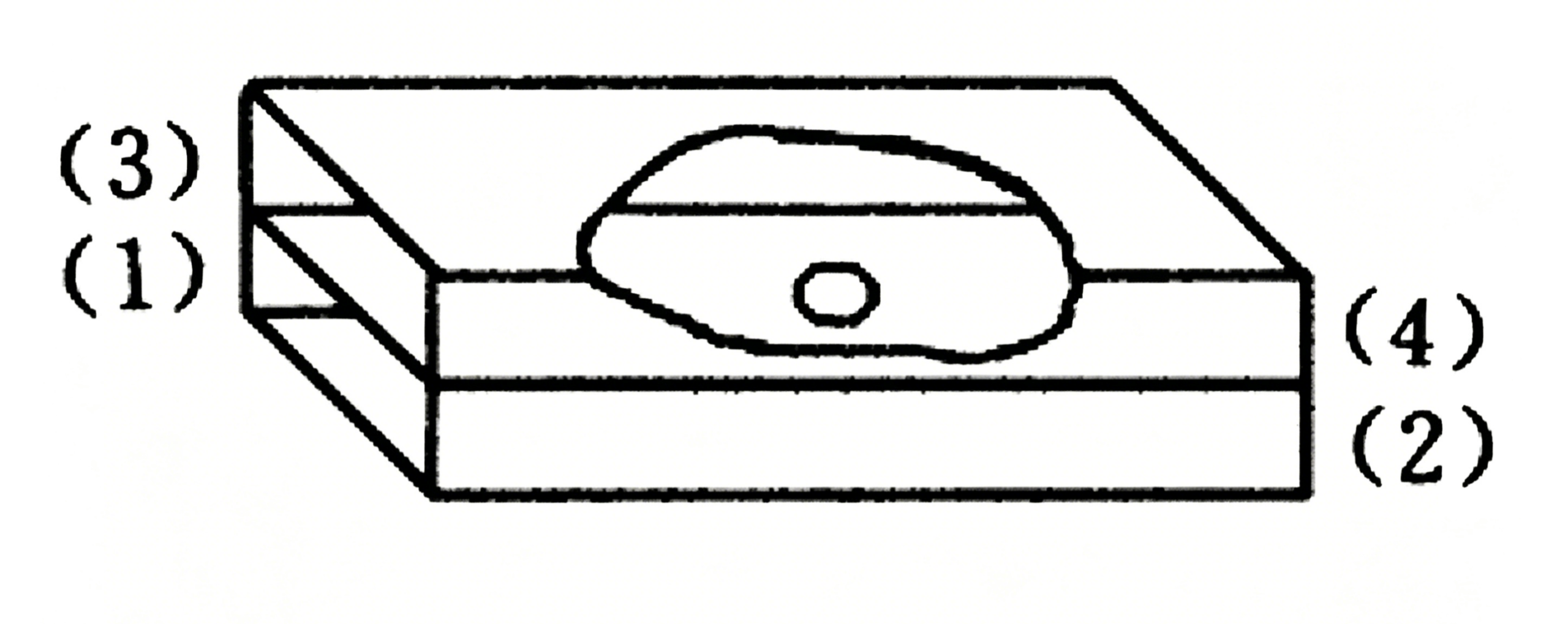
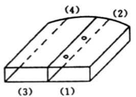
The structure of the single-hole directional coupler is shown in the figure above. The common wall between the main waveguide and the secondary waveguide is the wide wall. A circular coupling hole is placed at the centerline of the common wide wall.
Assume that the input signal has a TE10 mode waveform. Its mode pattern is shown in the figure below.When the TE10 wave enters the main waveguide from port 1, most of the signal energy continues to port 2. This port is called the through port.
A small portion of the signal energy is coupled through the circular hole into the secondary waveguide. Most of the coupled energy travels toward port 3, which is the coupled port.
Meanwhile, very little signal energy reaches port 4. Therefore, port 4 is called the isolated port.
For a single-hole directional coupler, the port functions can be summarized as follows:
- Port 1: Input port
- Port 2: Through port
- Port 3: Coupled port
- Port 4: Isolated port
But why does the signal behave this way? The reason lies in the electromagnetic field distribution and coupling mechanism inside the rectangular waveguide.
Electric and Magnetic Field Coupling Principle
First, take a look at the field diagram and the current distribution diagram below. Keep this in mind as we look for answers from the distribution of the electromagnetic field.
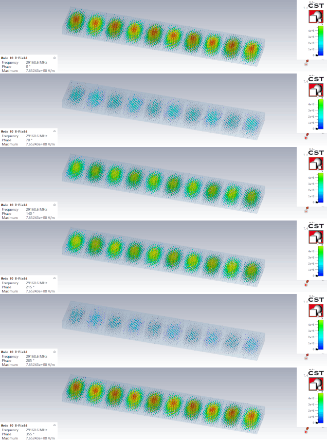
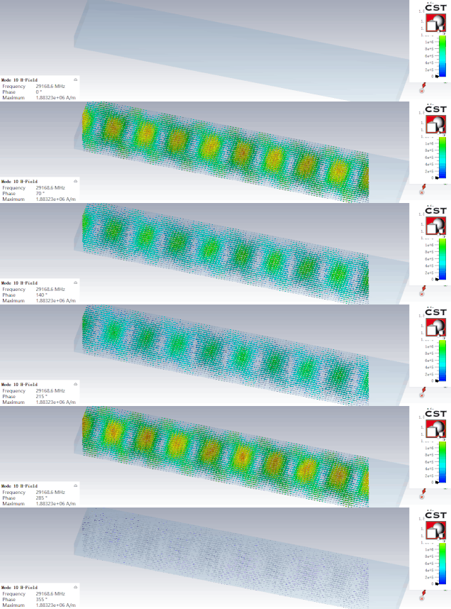
According to the electromagnetic field distribution of the TE10 wave in the rectangular waveguide, the electric and magnetic field distributions near the coupling circular hole are shown in the figure below.
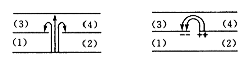
When the TE10 wave in the main waveguide reaches the coupling circular hole, part of the electric field energy E passes through the hole and enters the secondary waveguide. This creates an electric field distribution around the hole with the same magnitude and direction, as shown in Figure B above.
Because the circular hole is located on the centerline of the waveguide’s wide wall, the magnetic field also passes through the coupling hole into the secondary waveguide. The magnetic field distribution is shown in Figure C.
After the electromagnetic fields enter the secondary waveguide through the coupling hole, they combine and interact with each other.
As shown in the figure above, at port 3, the coupled electromagnetic signals are in phase. Therefore, they add together and become stronger.
At port 4, the coupled signals have opposite phases. As a result, they cancel each other out and become weaker.
Porous Directional Coupler
After introducing the single-hole directional coupler above, let’s move on to learn about multi-hole directional couplers. The rectangular waveguide multi-hole directional coupler described below has its main waveguide and auxiliary waveguide running parallel to each other, with a common wall being the narrow wall of the waveguide. Several small holes are opened in the common narrow wall at certain intervals. The simplest multi-hole coupler is the two-hole directional coupler, structured as shown in the figure below, with the distance between the two holes being a quarter of the wavelength of the center operating frequency.
When the electromagnetic signal enters from port 1, the TE10 mode in the main waveguide has only a longitudinal magnetic field component along the narrow wall, with no electric field component. Therefore, only one type of coupled wave passes through each coupling hole. To achieve directional coupling in the auxiliary waveguide, at least two coupling holes are needed. The wave transmission diagram is shown below.
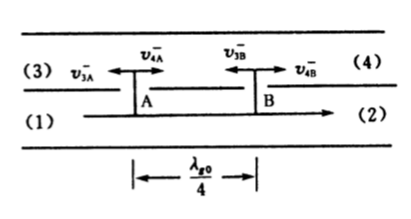
Let the waves coupled from hole A to the secondary waveguide be denoted as V3a and V4a. Since the coupling hole is very small, it can be assumed that the wave reaching hole B is approximately equal to the wave reaching hole A, just with a phase lag 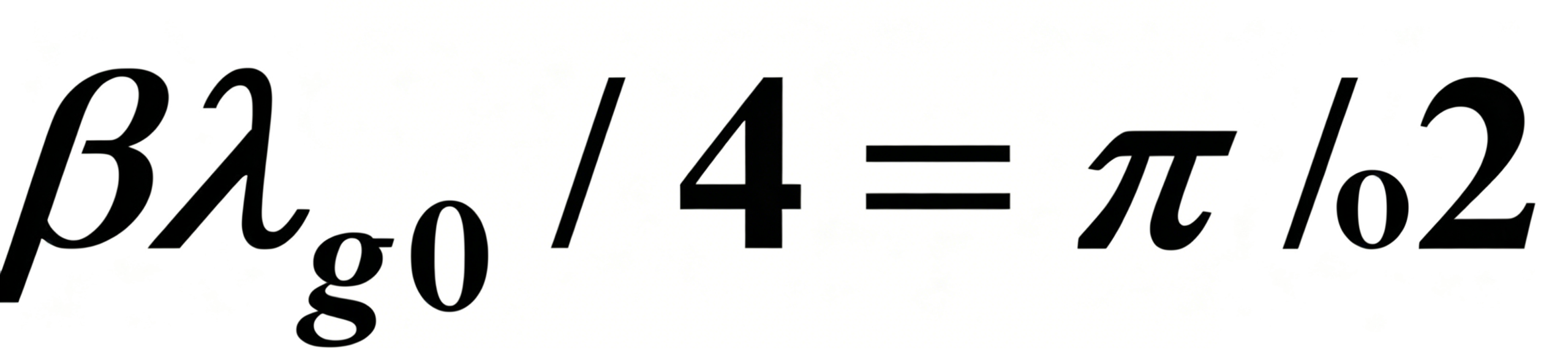 . In this way, the wave coupled from hole B to the secondary waveguide can be approximately expressed as:
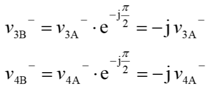
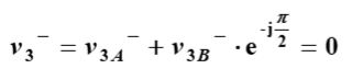
When V3b is transmitted to hole A and combined with V3a, its phase lags again, so the synthesized wave output from port (3) is:
Similarly, the composite wave output from port 4 is:

From the two equations above, we can see that port 3 is the isolated port, and port 4 is the coupled port.
From the analysis above, we can see that the directional coupling of a two-hole directional coupler is formed by the interference of waves coupled through the two holes, similar to the branch-line directional coupler introduced earlier.
Conclusion
Rectangular waveguide directional couplers provide an effective solution for high-frequency RF and microwave applications. Unlike transmission line-based directional couplers, waveguide couplers use electromagnetic field coupling through apertures in the waveguide wall to achieve signal distribution and monitoring.
In a single-hole directional coupler, the coupling mechanism is determined by the interaction between electric field coupling and magnetic field coupling. The superposition of these coupled fields creates signal enhancement at the coupled port and cancellation at the isolated port.
For multi-hole directional couplers, directional coupling is achieved through the interference of waves coupled from multiple holes. By carefully controlling the spacing and position of the coupling holes, engineers can achieve better directivity, coupling performance, and bandwidth characteristics.
Due to their low insertion loss, high power handling capability, and excellent performance at microwave frequencies, rectangular waveguide directional couplers are widely used in radar systems, satellite communications, and high-power RF applications.
Understanding the electromagnetic field distribution and coupling principles is essential for designing. Selecting the right waveguide directional coupler at ZR Hi-tech. With continuous development in microwave technology, waveguide structures remain an important approach for achieving reliable and high-performance RF signal coupling.



