Newsroom
How to Design an RF Power Divider: Complete Guide for High-Frequency Applications
The Principle of Power Dividers
A power divider is a passive microwave device primarily used for power distribution and combining. It divides an input signal into two or more output signals based on a defined ratio. The diagram below shows a common 1-to-2 power divider. The input power at port 1 is P1. The output power at port 2 is P2, and at port 3 is P3. Ideally, according to the law of conservation of energy, P1 = P2 + P3.
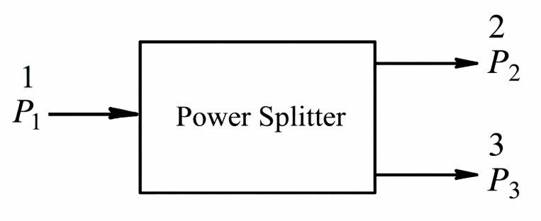
If the power divider described above is an equal-division power divider, i.e., P2 = P3, then the relationship between the power at the three ports can be written as:
P2 (dBm) = P3 (dBm) = P1 (dBm) – 3dB. Note the units; it cannot be written as P1 – 3dBm.
Technical Specifications of the Power Divider
The technical specifications of a power divider include frequency, power, distribution loss, insertion loss, isolation, and voltage standing wave ratio (VSWR) per port, also known as return loss. Operating frequency, power capacity, insertion loss, and return loss are mandatory specifications for every RF device. We will not discuss them in detail here. For power dividers, we will instead focus on two key parameters: distribution loss and isolation, and provide their definitions.
Distribution loss, the distribution loss from the main path to the branch path, is essentially related to the power distribution ratio of the power divider. For example, the distribution loss of a two-way power divider is 3dB, and the distribution loss of a four-way power divider is 6dB.
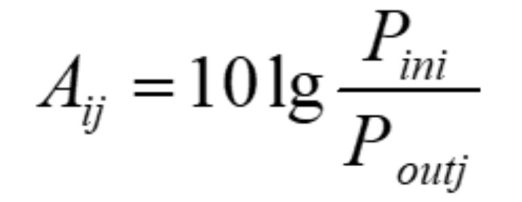
Definitions
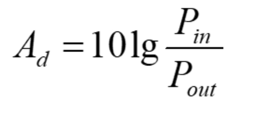
In the formula
![]()
In other words, the power distribution loss is the power allocation ratio between the input port and the output port.
Isolation between tributary ports is another important metric for power dividers. If power input from each tributary port should only be output from the main port and not from other branches, sufficient isolation between branches is required. When the main port and other branches are connected to matched loads, the isolation between port I and port J is defined as follows:
T-junction Power Divider
A T-junction power divider is a simple three-port network, as shown in the figure below, that can be used for power distribution and power combining.
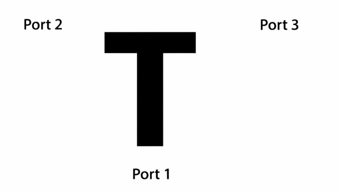
The “T” in this diagram refers to the signal entering from port 1. At the T-junction, the signal is split into two paths, exiting from port 2 and port 3 respectively. Based on the signal distribution ratio, power dividers can be classified as equal-distribution or unequal-distribution types. Of course, it can split a signal into two, or even more. You can even make it into a hedgehog configuration.
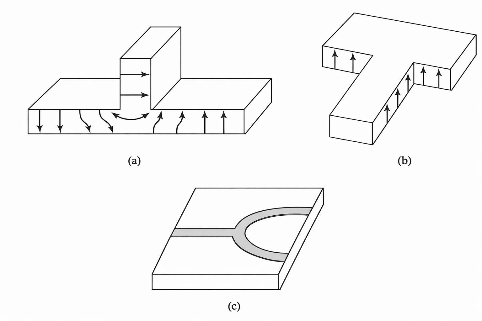
When implemented using transmission lines, a T-type power divider can be equivalent to a junction of three transmission lines, such as the three types shown in the figure below: E-plane waveguide T-junction, H-plane waveguide T-junction, and microstrip T-junction. At the junction, the discontinuity will excite stray fields or higher-order modes. If this discontinuity cannot be ignored, we can use an equivalent susceptance B to estimate the energy storage.
Its transmission line model can be equivalent to:
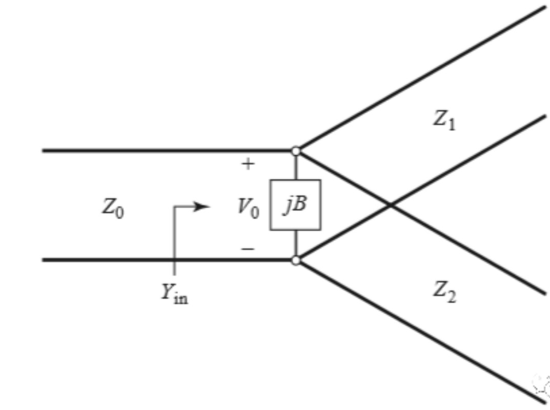
Impedance Matching and Power Distribution Analysis in T-Junction Power Dividers
Assuming the characteristic impedance of the transmission line at the signal input is Z0, and the impedances at the output are Z1 and Z2, then to ensure that the reflected signal is sufficiently small at the input, we need to match the equivalent impedance seen from port 1. That is, the parallel impedance of Z1 and Z2 equals the characteristic impedance Z0 of port 1.
At this point, the following needs to be met:
At this point, the signal will not be reflected at the T-junction. The power distribution ratio between port 2 and port 3 can be set according to the Z2:Z1 ratio. For example, in a 1:2 power divider, Z2:Z1 = 1. In this case, Z1 = Z2 = 2 × Z0. If the input impedance is 50 Ω, then Z1 = Z2 = 100 Ω. A quarter-wavelength impedance transformer is usually used in this case. It transforms Z1 and Z2 back to the desired impedance, such as 50 Ω. Note that the two output ports are not isolated in this type of divider. The impedances seen from the output ports are also mismatched.
For another example, in a 2:1 power divider, if the input impedance is 50 Ohms, the impedance of port 2 is Z1=150 Ohms, and the impedance of port 3 is Z2=75 Ohms. The impedance seen from input port 1 is the parallel impedance of Z1 and Z2, which equals 50 Ohms, meaning that input port 1 is matched. However, the parallel impedance seen from port 2 is 30 Ohms, and the parallel impedance seen from port 3 is 37.5 Ohms. These two ports are mismatched, and the reflection coefficient is:
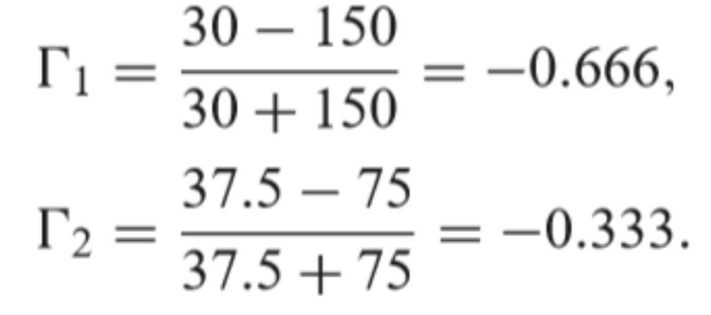
The return loss at port 2 is RL = 3.5dB.
The return loss at port 3 is RL = 9.5dB.
Common T-type Power Divider
Below are some common T-type power divider structure images collected for design reference. Take a look and see which ones you have used in your design.
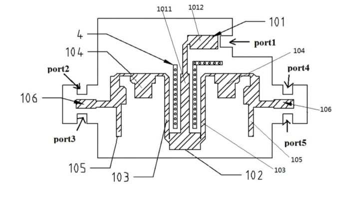
This is a power supply network for an antenna array. It uses a T-type power divider to split the signal from one to two, and from two to four, while simultaneously performing phase conversion.
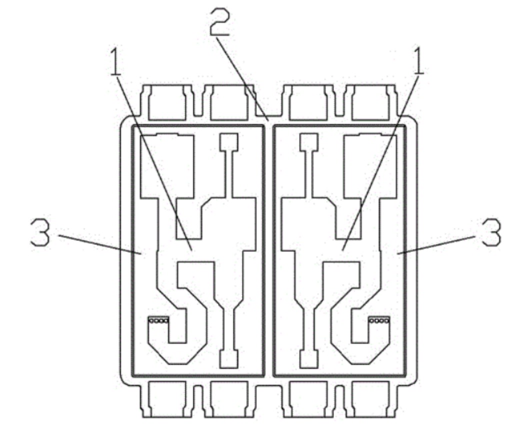
The following is a small-size ultrawideband power divider, from patent CN205646094U.
It includes a circuit board and a power divider circuit mounted on it. The power divider circuit has an input transmission segment connected to the input port, and two output transmission segments connected to the output ports. The input and output transmission segments are electrically connected through a circuit node. The signal transmission path length of both input and output segments is 1/6λ to 1/9λ. A line matching segment is also connected at the circuit node. Its length is 1/3λ to 1/6λ. This matching segment is used to match the line impedance. This design reduces the overall size of the power divider, making it suitable for more applications. It also reduces the effects of parasitic capacitance and inductance. In addition, it helps solve impedance mismatch caused by shortened transmission stubs, ensuring stable performance.
Conclusion
Power dividers are fundamental components in RF and microwave systems, enabling efficient signal distribution and combining across a wide range of applications. From basic principles such as power conservation and distribution loss to critical parameters like isolation and VSWR, understanding these core concepts is essential for successful design and system integration.
Among various implementations, the T-junction power divider stands out for its simplicity and flexibility. However, it also presents challenges, particularly in impedance matching and port isolation. Designers must carefully consider transmission line models, impedance ratios, and matching techniques—such as quarter-wavelength transformers—to achieve optimal performance.
As RF systems continue to evolve toward higher frequencies, wider bandwidths, and more compact designs, advanced structures and miniaturization techniques are becoming increasingly important. Whether applied in antenna arrays, satellite communications, or broadband systems, a well-designed power divider directly impacts overall system efficiency and signal integrity.
At ZR Hi-Tech, we are committed to delivering high-performance RF components, including power dividers, amplifiers, and filters, tailored for demanding applications.
Contact us today to learn how our RF solutions can support your next design.