Newsroom
Directional Coupler RF Power Measurement Errors: Causes and Analysis
Directional coupler is an essential tools for testing and characterizing RF systems. They are widely used to sample and separate RF signals without significantly affecting the main signal path. However, the limited directivity of a directional coupler can introduce measurement uncertainties and affect overall accuracy.
Directional couplers play a critical role in microwave and millimeter-wave applications. One common example is their use in vector network analyzers (VNAs). In these instruments, directional couplers separate and sample the forward and reflected waves traveling between the source and the device under test (DUT). This enables accurate characterization of parameters such as return loss, reflection coefficient, and VSWR.
Despite their importance, imperfect coupler performance can lead to measurement errors. In particular, limited directivity may cause unwanted signal leakage between ports, resulting in inaccuracies when measuring reflected power. This article explores how directional coupler directivity affects RF power measurements and examines the resulting sources of error.
Measuring the Reflected Power of a Directional Coupler
The figure below shows an example of a general directional coupler measuring the reflected power from an unknown load. Since we are measuring reflected power, the coupler’s load port (Port 1) is labeled as the input port, even though the source is connected to Port 2.
Use a directional coupler to measure reflected power. All four ports are shown, even though the isolation port is terminated.
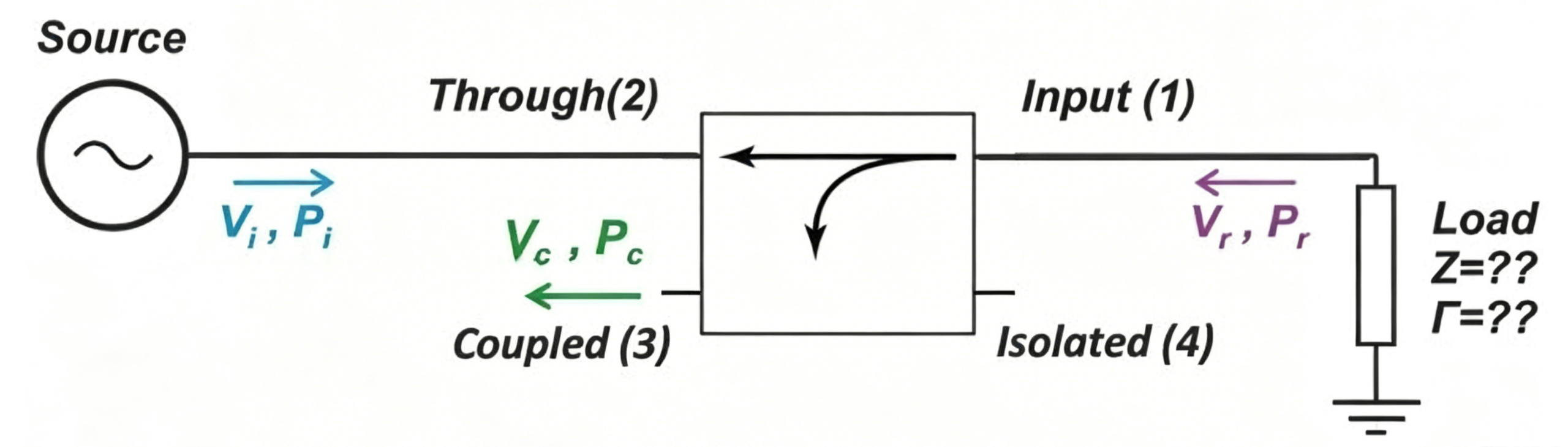
The power supplied (Pi) is transferred from port 2 to the load at port 1 through the coupler. At the load, part of the power is reflected back to the coupler due to the difference between the load impedance and the interconnection characteristic impedance. The amount of reflected power (Pr) depends on that difference. A small portion of the reflected power passes through the coupler and comes out from the coupled port (port 3).
Ideally, knowing Pi and measuring the coupled power (Pc) is enough to determine the load reflection coefficient (Γ). For example, if the load is perfectly matched, no power is reflected, so Pc should theoretically be zero.
However, in reality, a directional coupler will let some of the Pi that enters port 2 leak to the coupled port 3, which affects the accuracy of the power measurement. The amount of leakage depends on the coupler’s directivity. In the rest of this article, we’ll look into how to quantify this error.
A Review of Directional Coupler Equations
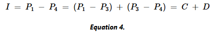
For the four-port directional coupler shown in the figure above, we can calculate these quantities in the following way:
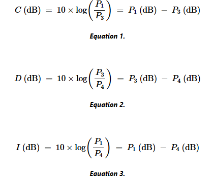
Here: Px represents the power of port x, measured in watts. Px (dB) represents the power of port x, measured in decibels. There’s an interesting relationship between these three factors:
Calculate the Reflected power of The Coupled Port
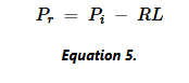
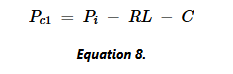
First, we’ll calculate the ideal power reaching the coupled port 3. Suppose all the power from the source (Pi) that hits port 2 comes out from port 1. Then, the power reflected from the load (Pr, in dB) equals the incident power (Pi) minus the load’s return loss (RL):
A portion of the input power on port 1 is coupled to port 3. By rearranging Equation 2, we can express the power coupled from port 3 like this:
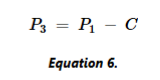
We call this coupled power supply on port 3 Pc1. Now, by applying Pr to P1, we get:
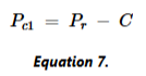
Finally, plug formula 5 into formula 7, and you get:
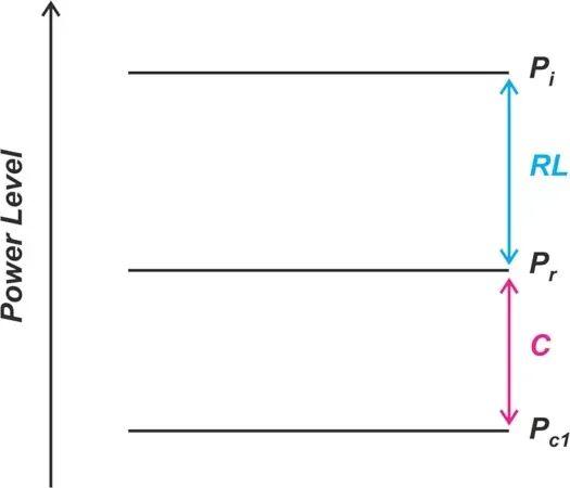
The picture below shows how power, coupling, and return loss are related.
In this analysis, we assume that the power reflected from the load and sent back through the coupler is completely absorbed by the coupler’s input port (Port 1). But in reality, that port might not be perfectly matched. So, multiple reflections between the coupler and the load could happen, which would further affect the measurement error.
Calculating Power Measurement Errors Caused by Limited Directivity
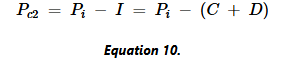
Now we need to start thinking about the sources of error in the coupler. Since the coupler has limited directivity, a small part of Pi also leaks to port 3. We call this leakage Pc2. For waves incident on port 2, port 3 is the isolated port. So, the amount of leakage is characterized by the isolation factor, and the equation is a bit different:
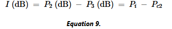
By rearranging this equation and substituting the expression from Equation 4, we get:
These relationships are shown in Figure 3. Pc1 represents the ideal signal for load return loss, while Pc2 is the signal leaking from port 2 to port 3.
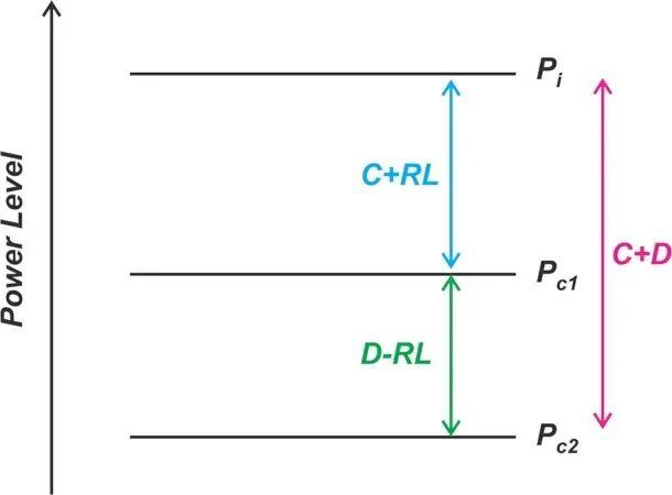
Pc2 exists only because the coupler has limited directivity. Ideally, the directivity (D) would be infinite, and the measured power would only depend on the load’s reflected power. When the directivity is limited, an extra power term (Pc2) appears at the coupling port, affecting our measurement accuracy.
As shown in Figure 3, the difference between Pc1 and Pc2 equals D – RL (directivity minus return loss). Given the directivity and return loss, we can easily figure out how much Pc2 is compared to the ideal power. For example, if D = 34 dB and RL = 26 dB, we know Pc2 is 8 dB lower than Pc1.
Consider The Phase Difference of The Directional Coupler
Above, we established the relationship between the ideal power measurement (Pc1) and the undesired leakage (Pc2). However, the total power measured at the coupled port also depends on the phase difference between these two signal components.
Assume that the voltage signals corresponding to Pc1 and Pc2 are sine waves with amplitudes of a and b, respectively. Using the relationship shown in Figure 3, we have:
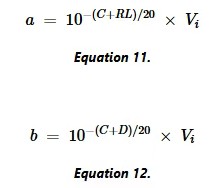
Here, Vi is the amplitude of the incident voltage coming from the source in the first diagram.
If the two signals are in phase, the overall signal amplitude will be a + b. On the other hand, if the two signals are 180 degrees out of phase, the overall amplitude will be a – b. These two extreme cases give the maximum and minimum values of the overall signal—the other phase differences will produce amplitudes somewhere between a – b and a + b.
The overall voltage wave at the coupled port can be represented as:
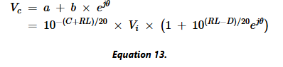
The terms in Equation 13 can be understood as follows: the ejθ term represents the phase difference between two signals.
The term inside the parentheses is the error factor, which characterizes the relative deviation between the measured and actual values.
The term in front of the parentheses represents the ideal amplitude we would get if the coupler had infinite directivity. We call this ideal amplitude Vdesired(ideal amplitude), and we write its equation separately:
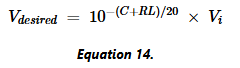
Then we can rewrite equation 13 as:
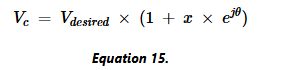
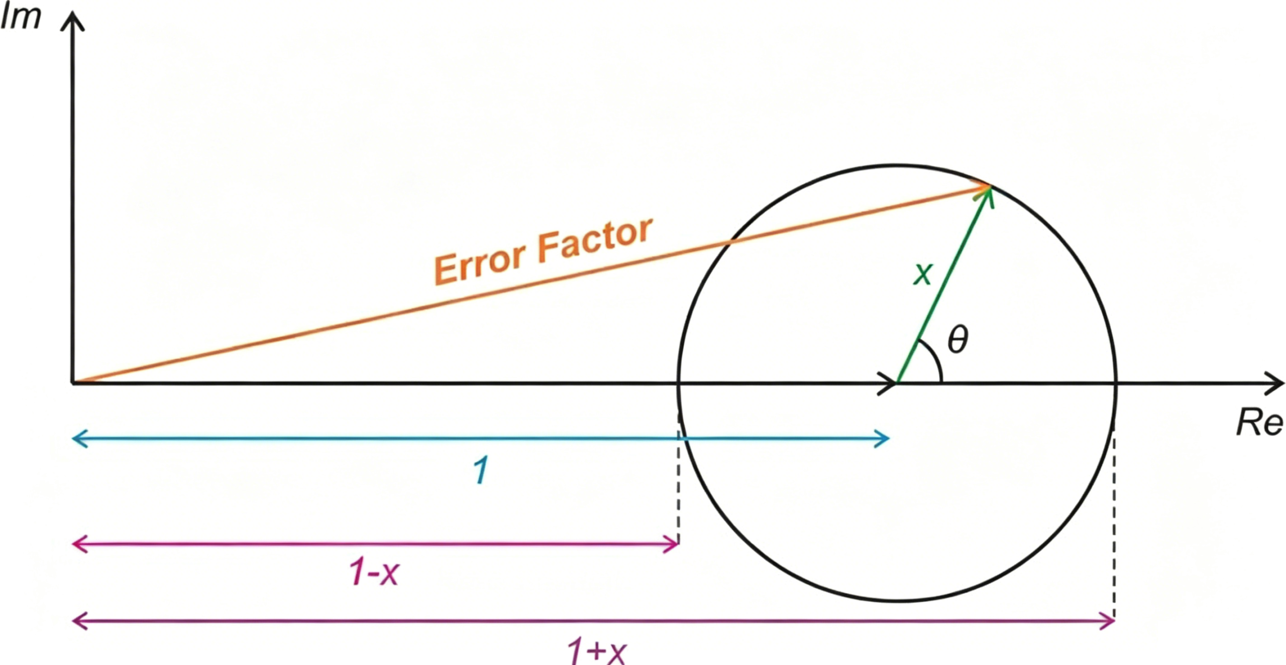
Here, x equals 10^(RL – D)/20. The overall error factor is the vector sum of 1 and x. Figure 4 helps us get an intuitive understanding of the error term.
Conclusion
Directional couplers are essential for accurate RF power, return loss, and VSWR measurements. However, limited directivity can introduce measurement errors by allowing unwanted signal leakage to reach the coupled port. The impact of these errors depends on the coupler’s directivity, the load return loss, and the phase relationship between signal components.
For high-accuracy RF testing, selecting a directional coupler with excellent directivity and low insertion loss is critical.
ZR Hi-Tech offers high-performance directional couplers with wide frequency coverage, low loss, and high directivity for applications in wireless communications, radar, satellite systems, and RF test equipment.
Contact ZR Hi-Tech today to find the ideal directional coupler for your RF measurement and monitoring needs.