Newsroom
Directional Coupler: Effects of Mismatched Coupling Ports on Key Parameters
Directional coupler are widely used in RF systems. They are used for signal sampling, power distribution, and monitoring. RF engineers often ask a common question: Does a mismatched coupled port affect the output power at the through port? In this article, we will answer this question clearly. We will start with basic circuit theory. Then we will derive the directional coupler’s S-parameters. This will help us understand the underlying mechanism.
S-parameters of The Directional Coupler
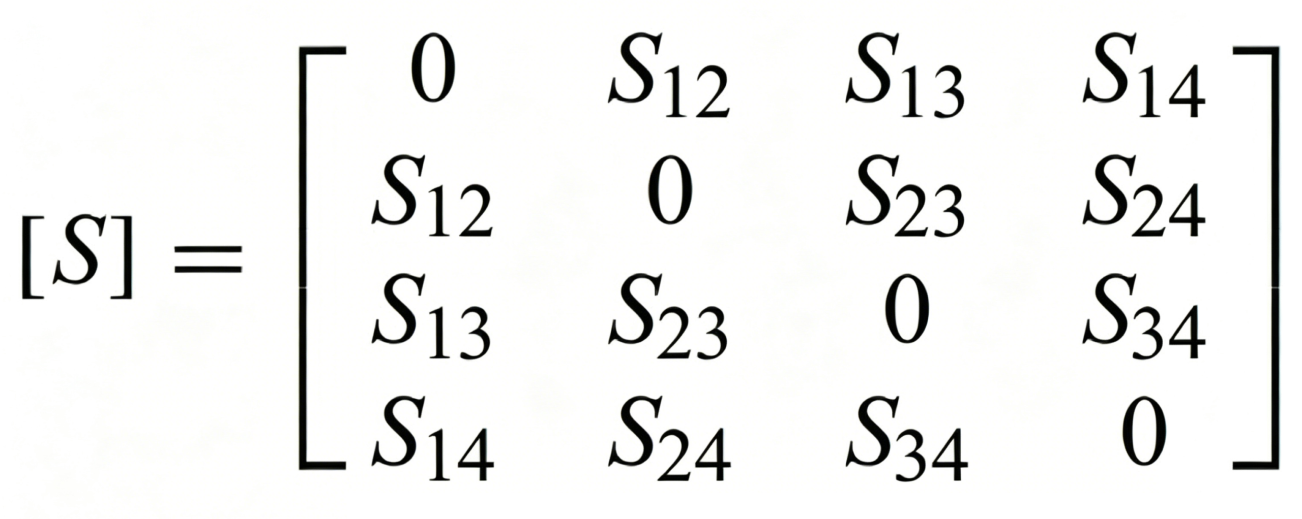
First, in a directional coupler, active devices, ferrites, and plasma are not included, so it is a reciprocal network. The S-matrix of a reciprocal network is a symmetric matrix, that is, S21 = S12, S13 = S31, etc. Assuming that each of its ports is perfectly matched, its S-parameters can be simplified to:
The insertion loss of the directional coupler is very small and can be ignored, so it can be assumed to be a lossless device. The S-matrix of a lossless device is a unitary matrix.
What is a unitary matrix? It is a matrix that satisfies the following equation, that is, the product of its transpose and conjugate matrix is the identity matrix.
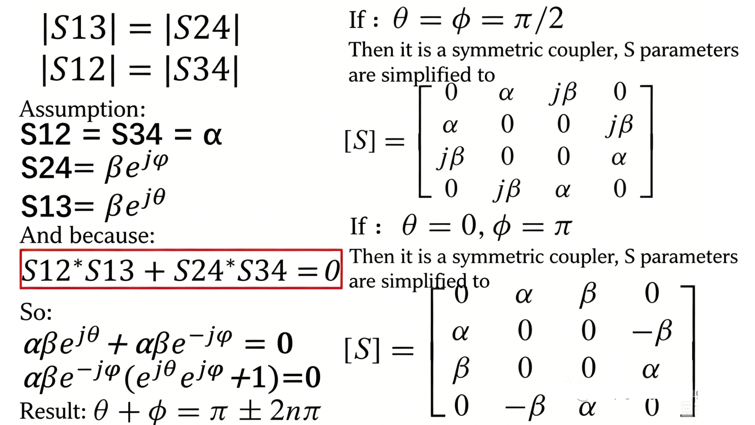
Then, based on the properties of unitary matrices, together with various simplifications, two common types of couplers are derived.
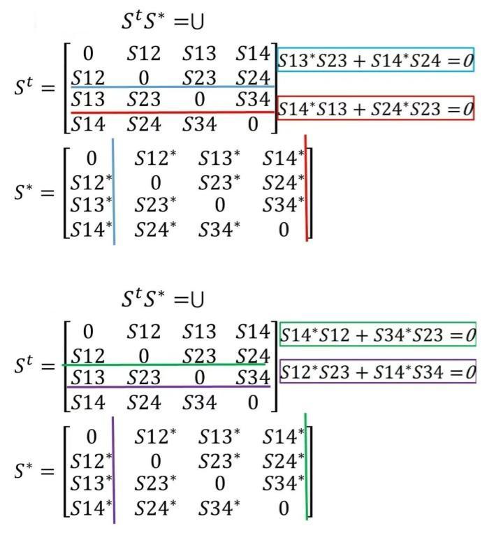
The S-parameters of the directional coupler can be further simplified, as shown in the figure below.
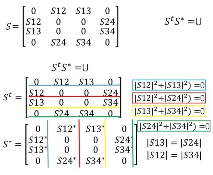
Multiply the rows and columns corresponding to each color to get the equation in the colored box in the above figure.
The derivation is complete, now let’s go back to the initial question.
Theoretical Inference
The S-parameters of the directional coupler also conform to the definition of S-parameters. Assuming an is the incident voltage and bn is the reflected voltage, the following expressions can be written.
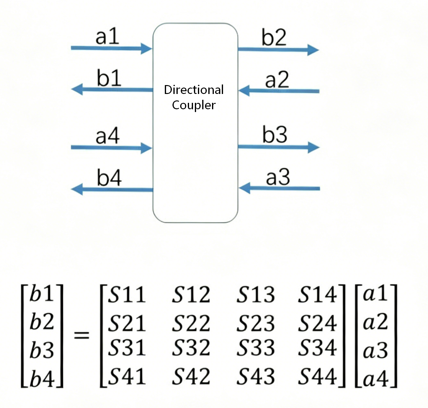
The coupled port is connected to a mismatched load, that is, a3 ≠ 0;
The input has a signal, that is, a1 ≠ 0; assuming a2 = a4 = 0, then b2 = S21 a1 + S23 a3;
From the above, it can be inferred that for an ideal coupler, S23 = 0, so if the coupler is ideal, connecting a mismatched load to the coupled port will not affect the output power.
The above is the theoretical deduction. Next, we will use ADS simulation to verify it.
Simulation Verification
First, build a schematic diagram, use the HB simulator to simulate the curve of the coupler’s output power as the termination resistance at the coupling port changes.
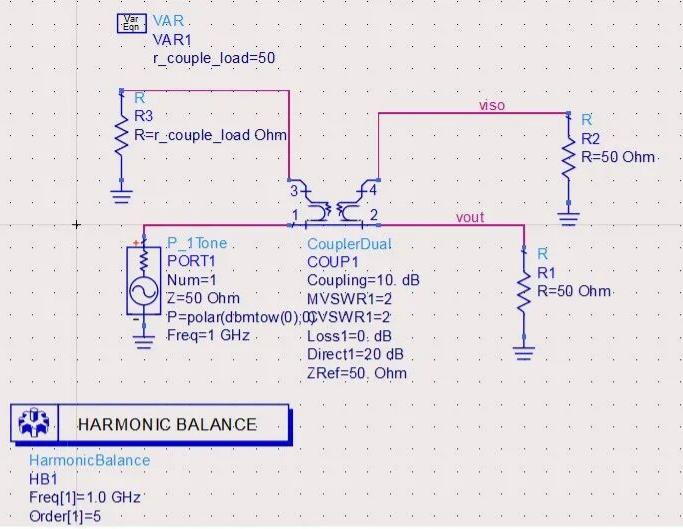
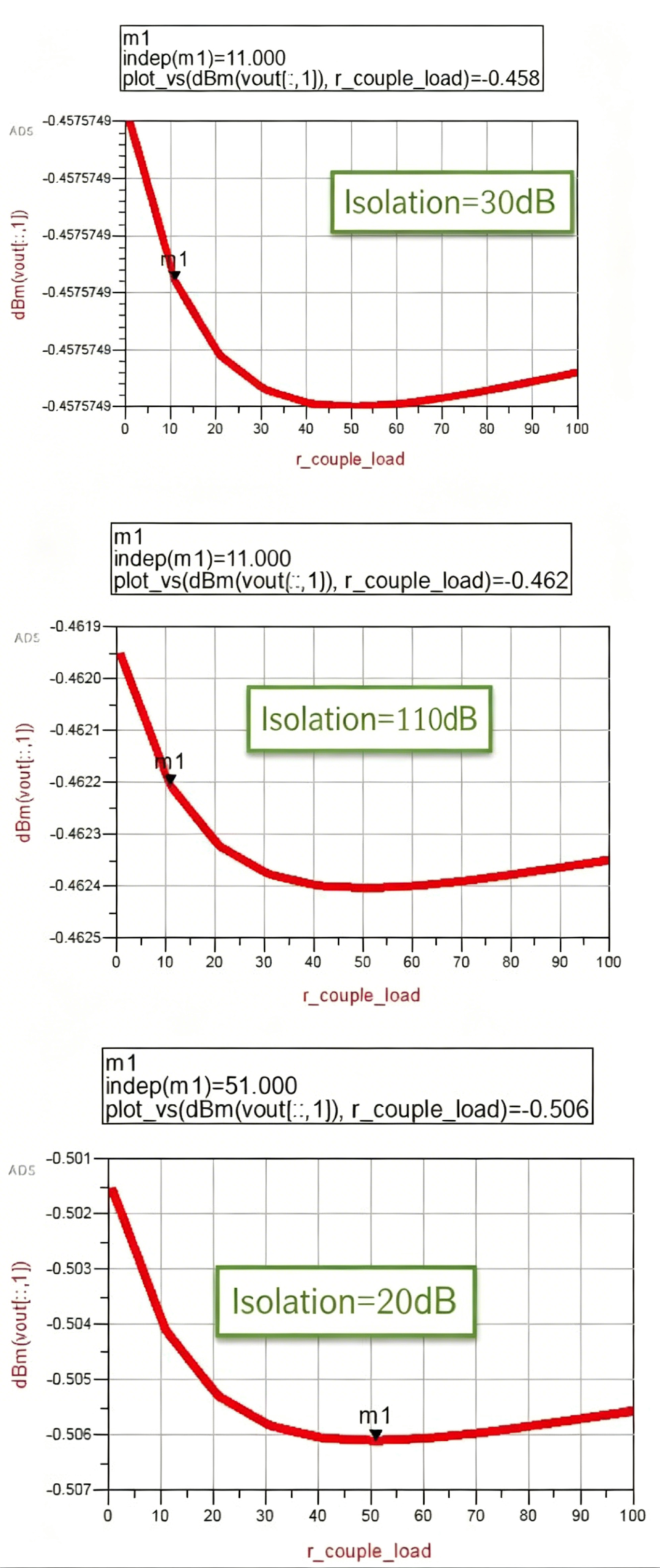
It can be seen that regardless of whether the isolation is 110dB, 30dB, or 20dB, the mismatch at the coupled port does not change the power at the output port.
Impact of Coupling Port Mismatch on Directivity
So when does the matching degree between the coupled port and its terminated load have a significant impact?
The main parameters of a coupler are insertion loss, directivity, coupling, isolation, and VSWR.
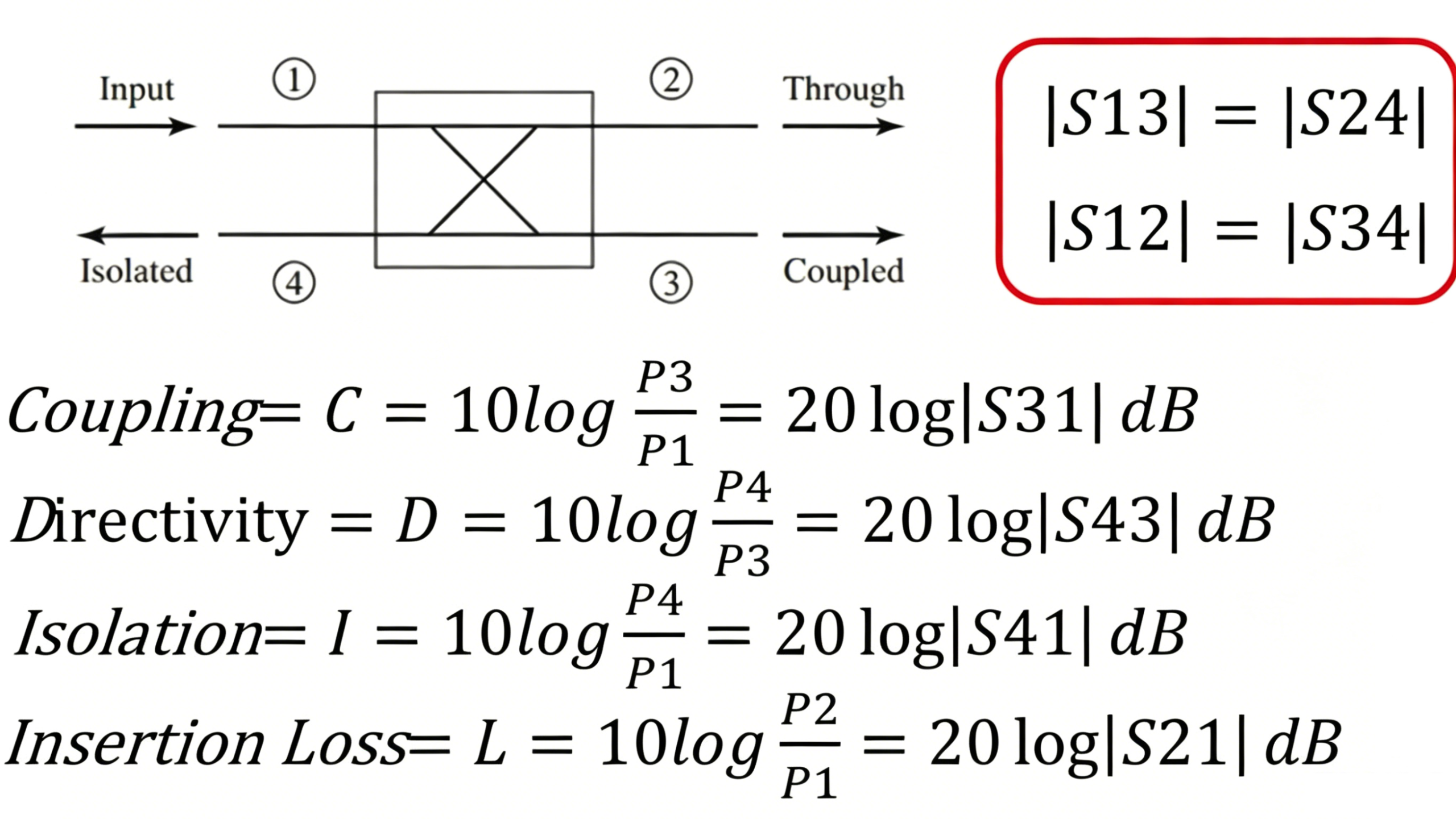
Assume that port 3 (i.e., the coupled port in the figure above) is connected to a mismatched load, and the signal reflected back is input to port 3. Since |S12| = |S34|, and because the directional coupler is a reciprocal network, we have |S12| = |S21| and |S34| = |S43|, so |S12| = |S34| = |S21| = |S43|.
In other words, the signal reflected back from the coupled port will pass directly to the fourth port (isolated port) if the insertion loss is 0. This will cause the directivity of the directional coupler to deteriorate.
If your circuit needs to detect standing waves, which is the ratio of the reflected signal to the incident signal, then this directivity parameter becomes very important.
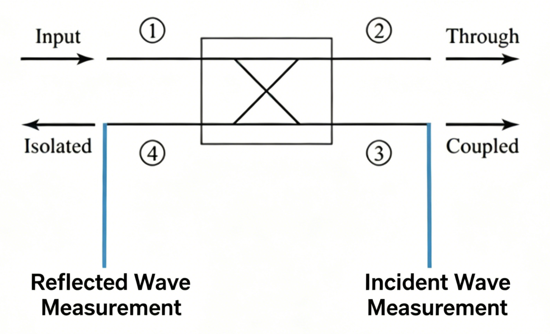
Originally, the amplitude of the signal at the isolated port represents the energy of the reflected wave. If the energy from your coupled port is reflected through the load and reaches the isolated port, the signal measured at the isolated port will be inaccurate.
The directional couplers in a vector network analyzer have very high requirements for directivity. The better the directivity, the more accurate and stable the measured parameters will be.
Conclusion
Both theoretical derivation and ADS simulation confirm this. The through-port power remains stable, no matter how well the coupling port is matched.
This is especially true in high-precision tools like vector network analyzers. In these instruments, accurate sampling of incident and reflected waves depends on well-isolated ports.
If you have further questions about directional coupler design, simulation, or optimization, feel free to reach out to the team at ZR Hi-tech for professional support.