Newsroom
Complete Guide to RF Power Divider Design with ADS, CST and HFSS Simulation
If we liken communication planning protocols to traffic lights and data transmission to cars driving on highways, radio frequency hardware acts like road surfaces supporting the whole traffic system. As core components of communication systems, microwave passive devices greatly affect overall system performance. RF Power divider split one input signal power into multiple branches at set ratios. They are widely used in RF and microwave systems, and play a vital role in RF feed networks.
Concept of RF Power Divider
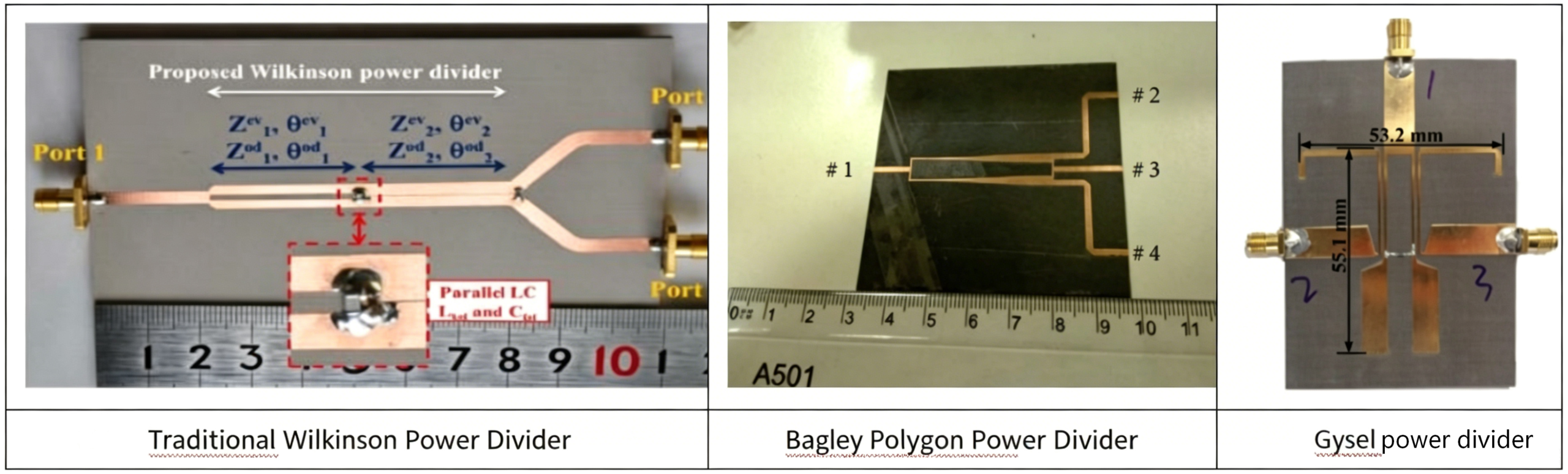
A power divider mainly splits single input signal power into multiple outputs at fixed ratios. Its output ports need high isolation to prevent signal crosstalk. First developed in the 1940s, power dividers have been continuously optimized for better performance. Typical types include Wilkinson, Bagley polygon and Gysel power dividers. Thanks to superior performance, Wilkinson power dividers are widely adopted in RF and microwave communication systems. They are mainstream microwave passive components. Most current optimization researches are also focused on upgrading traditional Wilkinson structures.
Origin of the Wilkinson power divider:
In 1960, E.J. Wilkinson first invented the Wilkinson resistive power divider, which has high isolation characteristics compared to the T-junction.
In 1968, S.B. Cohn first proposed using a multi-stage stepped impedance transformer to expand the bandwidth of the Wilkinson power divider. By using even-odd mode analysis, the principle of implementing a wideband circuit was explained, and specific design methods and results were provided. Subsequent researchers only need to refer to tables to easily design high-performance wideband power dividers. For a four-stage Wilkinson power divider, the bandwidth can even exceed 10:1, meeting the requirements of most communication systems.
In 1977, Nobuo Nagai first proposed a planar structure power divider. With the continuous advancement of printed circuit technology, planar transmission lines and isolation resistors replaced the previously bulky coaxial structure. The characteristics of easy processing and integration have led to the widespread application of PCB-based power dividers.
Recent Developments in RF Power Divider
1. Using a slow-wave structure power divider
The main way to realize a planar slow-wave structure transmission line is to load meander lines, interdigital capacitors, spiral inductors, defected ground structures, electromagnetic bandgap structures, etc., on microstrip, coplanar waveguide, and substrate integrated waveguide transmission lines in order to increase the equivalent lumped capacitance and inductance on the transmission line, thereby achieving miniaturization.
For example, when implementing a 4:1 Wilkinson power divider, a microstrip line with an impedance of 158 ohms is required. For conventional manufacturing processes, creating a microstrip line with an impedance over 100 ohms is extremely difficult because the line width becomes very narrow and is hard to fabricate. In 2001, Jong-Sik Lim and others used the traditional Wilkinson power divider topology along with a Defected Ground Structure (DGS) design to increase the characteristic impedance of the microstrip line. This principle allows such microstrip lines, compared to conventional microstrip lines without DGS, to achieve a higher characteristic impedance at the same conductor width, thereby overcoming the physical limitations of the manufacturing process.
2. Use a RF power divider with lumped parameter components or open-circuit branches
This method mainly involves replacing part of the transmission lines in a conventional Wilkinson power divider with lumped element circuits, or adding lumped element components to the circuit, so that the power divider can be miniaturized while still achieving ideal performance.
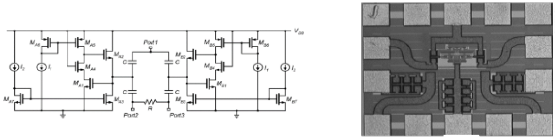
In 2005, Liang-Hung Lu and others designed a miniaturized power divider using 0.18um complementary metal-oxide-semiconductor (CMOS) technology. In this design, the traditional Wilkinson power divider’s quarter-wave impedance transformer is first converted into a lumped element circuit by using a T-type transmission line equivalent, and then active inductors are used as the lumped element inductors in the circuit. Since there are no distributed transmission lines or spiral inductors in the circuit, its area is greatly reduced. This structure achieves a return loss better than 30dB and an insertion loss better than 0.16dB at the center operating frequency of 4.5GHz, demonstrating excellent performance.
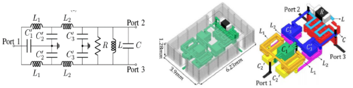
In 2021, M.L. Laurenzid et al. designed a compact dual-band power divider for global navigation satellite systems with LTCC technology. LTCC features high dielectric constant and low loss, similar to semiconductor compounds. Yet it cannot fabricate transistor structures, so it is mainly applied to miniaturized microwave passive components.
3. Use the improved impedance converter
This method replaces the impedance transformer in a traditional power divider with an improved structure to achieve miniaturization of the power divider or to reduce the distributed parameter effects caused by lumped RLC components.
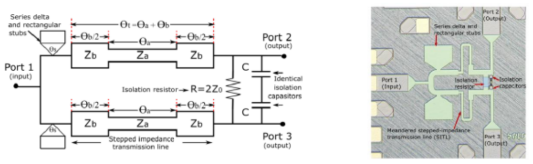
In 2021, Nethini Weerathunge and others designed a miniaturized power divider for MMIC using stepped impedance lines and short-circuited lines, and used a capacitor network to improve the isolation between output ports. Measurements showed that in the frequency range of 5GHz to 43GHz, the return loss of this structure is better than 10dB, and the isolation between output ports is better than 10dB in the frequency range of 20.3GHz to 43GHz. Compared with the traditional Wilkinson power divider, the size of this structure is reduced by about 57%.
4. Use advanced technology to achieve miniaturization and improve performance
This method mainly utilizes various advanced processes to make the impedance transformers of power dividers meander or be split into multi-layer structures, replacing lumped RLC components, which makes the layout of the power divider more compact and thus reduces the circuit area.
In 2019, J. Tayebpour and other scholars designed a high-power miniaturized Wilkinson power divider operating in the VHF band. In this design, the authors proposed a compact multi-layer structure, which consists of two ground planes and three signal layers connected by vias, with two Wilkinson branches implemented in two different layers and combined at the bottom layer. The quarter-wave impedance transformers of the power divider were designed as meandered transmission lines, effectively reducing the circuit size. Since there are no reactive lumped components in the circuit, it can be used in high-power scenarios.
Case Applications of RF Power Divider
Case 1: Application of Unequal Power Divider
For example, common application background: When synthesizing a passive antenna array aperture, the feeding network design is carried out according to specific sub-array power ratios, that is, the application of unequal power dividers.
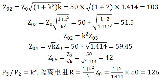
1. Suppose there is an 8-subarray linear array for Chebyshev synthesis, with a main-to-sidelobe level ratio of 20dB.According to the current amplitude ratio, the unequal power divider implements an 8-port feeding strategy:
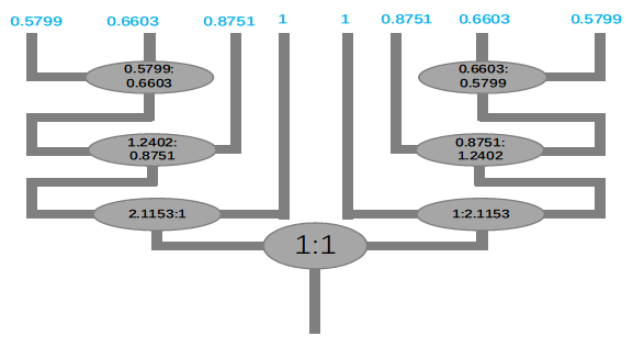
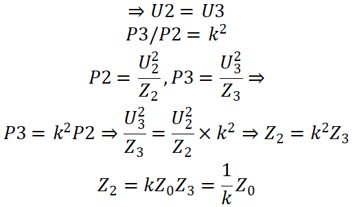
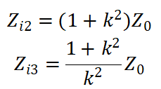
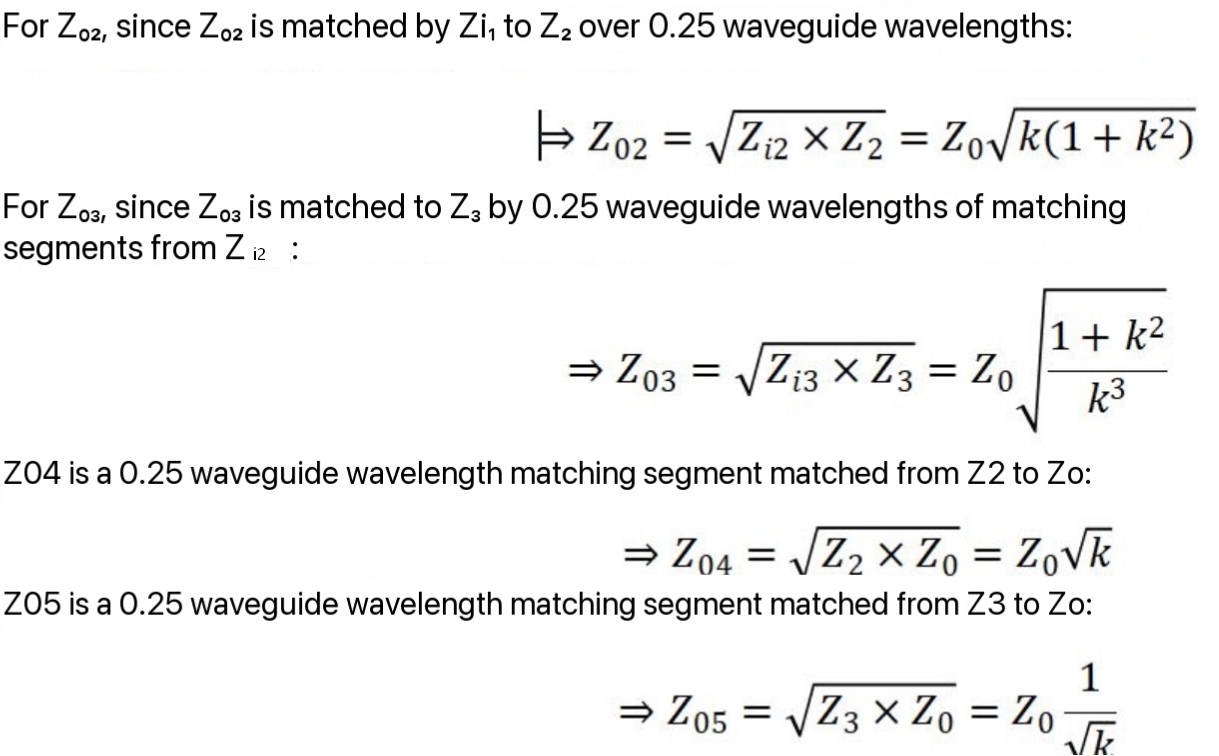
It can be seen that this feed network is obtained by cascading 1-to-2 power dividers with arbitrary power ratios. The Wilkinson topology of such unequal power dividers and the related formula derivation are as follows (power ratio is k^2, voltage ratio is k),Since the output port is completely isolated, the potential difference across the isolation resistor R is 0.
(1)
Since there is a complete match between the ports, there is no potential difference on R, thus satisfying:
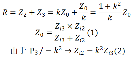 Solve equations (1) and (2).
If we master the design method of a 1-to-2 power divider with arbitrary power ratio, then the feeding network of a passive antenna array during array pattern synthesis can also be easily mastered.
Case 2: Design and Simulation of a Two-Way Power Divider
For example, consider a two-way power divider operating at 2.4-2.5 GHz (covering low-frequency Wi-Fi). The requirements are a VSWR of less than 1.3 across the bandwidth, a power ratio of 1:2, isolation greater than 20 dB, and port impedance of 50 ohms. The general design rule is to derive theoretical values using circuit topology, verify the theory with circuit simulation software such as ADS, and then verify the performance results using field simulation software like CST HFSS. Once reasonable consistency is achieved, a prototype is manufactured.
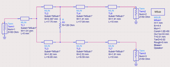
1. Use the previous derivation results to perform a preliminary calculation of this theoretical topology
2. Use ADS to build the transmission line simulation model on the PCB board, and check relevant indicators such as the standing wave on the main line, branch insertion loss, isolation, and branch phase difference. It can be seen that the branch loss at port 2 is 5dB, and at port 3 is 2dB. The amplitude difference of 3dB between the two branches corresponds to a power difference of half, which matches the expected theory.
3. Convert the road simulation model into a field simulation model of the actual physical model, and then check the consistency of the corresponding indicators between the field and the road again.
The above article is realized through theoretical derivation, circuit simulation verification, and field simulation verification. It proposes a design metric and gradually completes the modeling to achieve a complete simulation demonstration of the integrated process, wishing you quickly master the design methods of RF passive devices from scratch.
Conclusion
As vital passive components, RF power dividers are widely applied in communication feed networks. This article introduces their basic principles, classic classifications and research progress, and summarizes practical miniaturization and performance optimization methods. Combining theoretical design with ADS circuit simulation as well as CST and HFSS electromagnetic simulation can efficiently complete power divider design and performance verification. With the booming development of wireless communication, power dividers keep evolving towards miniaturization, wide bandwidth and high efficiency. If you have relevant design demands or technical consultation needs, feel free to contact ZR Hi-tech for professional solutions and technical support.