Newsroom
Wilkinson Power Divider: Full Detailed Explanation, Features and Uses
The Wilkinson power divider is a relatively commonly used RF device, proposed by RF engineer E.J. Wilkinson in an article in 1960. The Wilkinson power divider has a common application. It can split a single signal into two signals at a fixed ratio. It can also combine two separate signals into one. We already know one basic RF principle: a standard three-port network cannot achieve full matching on all ports. To solve this problem, Wilkinson added a resistor between Port 2 and Port 3. This simple design realizes perfect matching for all three ports. When the device works as a power divider, the resistor does not affect signal performance. However, when it acts as a combiner, the resistor will consume and dissipate part of the power. Why does this happen? We will explain the working principle in detail below.
Even-Odd Mode Analysis of the Wilkinson Power Divider
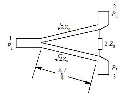
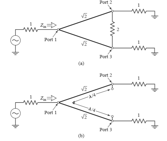
The above image is a traditional equally divided Wilkinson power divider. Let’s take a look at how Wilkinson solves this problem.
The book 《Microwave Engineering》 adopts even-odd mode analysis for the Wilkinson power divider. Even-odd mode analysis is the most widely used method in microwave circuit design. It is complicated to analyze the Wilkinson power divider with single-port input directly. Instead, the input signal can be decomposed into the superposition of even mode and odd mode. In odd-mode analysis, it is equivalent to adding a ground plane between the two transmission lines. In even-mode analysis, the two lines operate in parallel. This way, circuit and electromagnetic field analysis can be performed on a single transmission line. Based on the linear superposition principle of circuits, we combine the influences of even mode and odd mode to get the final analysis result.
Today, let’s study together the basic principles of the Wilkinson power divider using the ‘even-odd mode analysis method’.
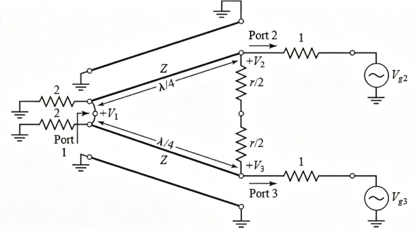
First, normalize the circuit diagram of the Wilkinson power divider. Why normalize it? After normalization, it has universality.
Wilkinson Power Divider Even-Odd Mode Theoretical Derivation
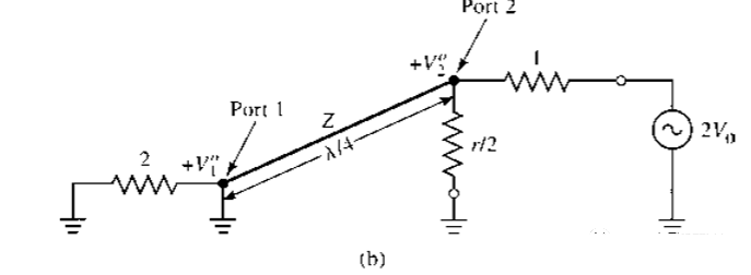
First, consider the odd-mode excitation Vg2 = Vg3 = 2V0, so V2e = V3e. The voltage across resistor r is equal, and no current flows through resistor r, so there is a short circuit between the two transmission line inputs at port 1. Therefore, the above diagram can be divided into a normalized circuit as shown in the figure below.
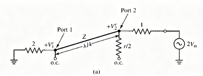
At this time, the impedance seen from port 2 is:
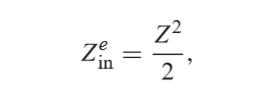
It’s very simple. If Z equals the square root of 2, then Zine equals 1, so port 2 is matched, and V2e equals V0. V1e can be calculated according to the transmission line equation.
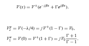
At port 1, the reflection coefficient ┏ is: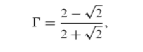
So: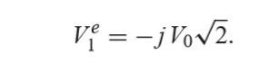
Wilkinson Power Divider Odd-Mode Analysis
Next, perform odd-mode analysis. For odd-mode excitation, Vg2 = -Vg3 = 2V0, so V2o = -V3o; the voltage at the center line of the normalized circuit is zero, so the circuit is divided into two parts, as shown in the figure below:
The impedance seen from port 2 is r/2. This is because port 1 is short-circuited, and through the quarter-wave transformer, it is equivalent to an open circuit at port 2. For an equal power divider, if r=2, then r/2=1, making port 2 matched. At this point, V2o=V0 and V1o=0.
For this excitation mode, all the power is transmitted to the resistor r and none enters port 1. For an equal power divider, the upper and lower parts are symmetrical, so we can also see that port 3 is matched.
Then is port 1 matched? When ports 2 and 3 are connected to matched loads, what is the input impedance at port 1? The equivalent circuit is shown in the figure below. Since V2=V3, no current flows through resistor r, which can be directly ignored. Only the circuit related to b remains. At this point, it becomes simple.
From port 1, it looks like an impedance formed by two quarter-wave transformers with an impedance of 1 connected in parallel. Therefore, port 1 is also matched.
Intuitive Signal Flow Explanation and Simulation Validation
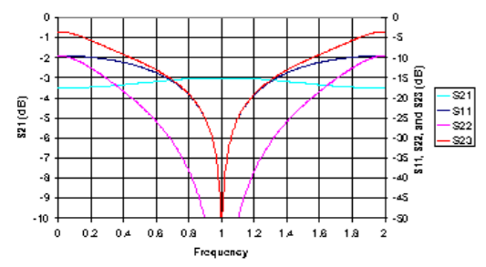
It is unclear whether all the calculations mentioned above are dizzying. In engineering, there are always better ways to understand things. We can use simulation software to simulate and observe the flow diagram of the electromagnetic field, and we can also obtain the S-parameters of each port.
The corresponding S-parameter is that, at the operating frequency point, each port achieves perfect matching, ports 2 and 3 are ideally isolated, and the power is divided equally by 3 dB.
Here’s the simplified, split-up version, keeping the technical meaning intact: The working principle of the Wilkinson power divider can also be explained intuitively with a signal flow diagram. The input signal at Port 1 is split equally into two paths to Port 2 and Port 3. At this point, the signal voltages on both sides of the isolation resistor are identical. Because of this, no current flows through the resistor. The two output ports appear as parallel loads at the input. To combine into the input impedance \(Z_0\), each output port must present an impedance of \(2Z_0\) at Port 1. This impedance transformation is achieved by a quarter-wave transformer. Without this transformer, the parallel combination of the two outputs would only give \(Z_0/2\) at Port 1. For the input to match properly when Ports 2 and 3 are terminated with \(Z_0\), the quarter-wave line must have a characteristic impedance of \(\sqrt{2}Z_0\) (≈1.414 × \(Z_0\)).
Conclusion
The Wilkinson power divider is a cornerstone component in modern RF and microwave systems. From its elegant solution to the three-port matching problem to its versatile use as both a power splitter and combiner, its design principles remain as relevant today as when E.J. Wilkinson first proposed them in 1960. We’ve broken down its core working mechanism, even-odd mode analysis, and key performance characteristics like matching, isolation, and equal power division. While the resistor enables perfect port matching, it also introduces inherent power loss when combining signals—a tradeoff every RF engineer must consider in their design. Whether you’re working on communication systems, radar, or test equipment, understanding these principles is critical to optimizing performance. If you’re looking for high-performance, reliable microwave components tailored to your project needs, ZR Hi-tech offers professional microwave solutions designed to meet the most demanding specifications. Our team can help you select or customize power dividers, couplers, and other RF components to ensure optimal system performance. Ready to take your RF design to the next level? Contact us today to discuss your requirements and discover how ZR Hi-tech can support your engineering goals.