
Newsroom
The Importance of Directional Couplers in Distributed Antenna Systems
In 5G indoor coverage projects, many engineers focus on the base station’s transmit power. Others pay close attention to the gain of the optical fiber repeater. However, a critical passive RF component is often overlooked—the directional coupler.
If power dividers are installed at every node without careful planning, signal distribution quickly becomes unbalanced. Rooms close to the equipment room may receive excessively strong signals. This can lead to interference and dropped calls. Meanwhile, rooms at the far end of the building may suffer from weak signals or even complete coverage blind spots.
The success of a Distributed Antenna System (DAS) depends on precise RF power distribution. In other words, it is a matter of accurate power control rather than simply increasing transmit power.
In this article, we will use real engineering examples to explain how directional couplers solve the key challenges in DAS deployment. We will also show why they are essential for achieving balanced indoor coverage and reliable network performance.
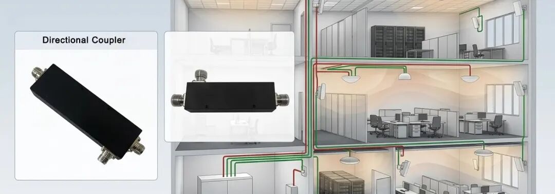
‘Near-far Effect’ in DAS Links
In a typical multi-story Distributed Antenna System (DAS), the RF signal travels from the equipment room to the upper floors through a main trunk cable.
- The Limitation of Power Dividers: If a two-way power divider is installed at every node, the signal power is reduced by approximately 50% at each split. After passing through five nodes, less than 3% of the original signal power remains in the trunk cable. As a result, the upper floors receive very little usable RF energy. This often leads to weak coverage and poor network performance.
- The Directional Coupler Solution: A directional coupler has a main line and a coupled port. Most of the RF power continues along the main line. Only a small portion is coupled to the antennas on each floor. This design preserves signal strength for downstream nodes. At the same time, it provides sufficient power for local antenna coverage.
- Real Engineering Example: In a 5G DAS project for a large shopping mall, engineers deployed directional couplers with different coupling values. They installed 15 dB couplers near the signal source. 10 dB couplers were used in the middle of the network. 6 dB couplers were placed near the end of the trunk line. After optimization, the output power variation across more than 30 antenna nodes was kept within ±1.5 dB.
This is a good example of power flattening. By selecting appropriate coupling values, directional couplers distribute RF power evenly throughout the entire DAS.
Isolation: Protecting Expensive 5G Base Stations
5G carrier aggregation (CA) is highly sensitive to return loss and signal reflections. If a branch antenna is damaged, reflected signals can travel back through the RF network. The same problem can occur if an RF connector is loose or poorly connected. These reflected standing waves may reach the base station. As a result, they can degrade system performance.
- Isolation Protection with Directional Couplers: A high-quality directional coupler provides excellent directivity. Most reflected signals are canceled or confined inside the coupler. Only a small portion of the reflected energy returns to the main transmission line. This significantly reduces the amount of reflected power reaching the base station.
- Engineering Benefits:This physical-layer isolation helps protect the RF power amplifier (PA) from excessive reflected power. It also improves system reliability by reducing errors caused by impedance mismatches. As a result, directional couplers play an important role in maintaining stable performance in 5G Distributed Antenna Systems (DAS).
Low Intermodulation Stability
In distributed antenna systems, couplers are key components that handle high power from multiple carriers. If the nonlinear effects inside the coupler are severe, the resulting passive intermodulation can directly overwhelm the 5G receiver’s noise floor. According to ZR Hi-tech’s tech standards: we don’t talk about ‘average values,’ we only focus on ‘dynamic stability.’
- Materials: we gave up magnetic stainless steel and fully use non-magnetic brass and aluminum alloys.
- Plating process: we use ternary alloy plating to prevent contact nonlinearity caused by electrochemical corrosion.
- Performance endorsement: our directional couplers can stably reach -161 dBc under a 2×43 dBm test. During on-site knock tests, the PIM fluctuation is less than 2 dB.
Scenario Test: When Do You Have to Choose A Directional Coupler?
Based on engineering experience from numerous Distributed Antenna System (DAS) projects, directional couplers are particularly valuable in the following scenarios.
A. Vertical Elevator Shaft Coverage
Elevator shafts are typically long and narrow. Maintaining consistent signal strength throughout the shaft is challenging. Directional couplers distribute RF power gradually along the feeder cable. This design enables smooth signal handover as the elevator moves between floors. It also prevents coverage failures caused by large power differences between adjacent nodes.
B. Signal Sampling for Network Monitoring
During system maintenance, engineers often need to monitor live downlink signals. A 20 dB or 30 dB directional coupler can be installed in the RF link. It extracts a small sample of the signal for measurement equipment. Meanwhile, the main transmission path remains virtually unaffected. This allows real-time monitoring without interrupting normal network operation.
C. Multi-Operator POI Systems
Many indoor networks support multiple mobile operators through a Point of Interface (POI) system. Each operator requires accurate RF power balancing. Directional couplers with different coupling values provide precise signal adjustment. This helps optimize overall system performance and coverage consistency.
Successful DAS design requires precise RF power distribution. Selecting the right directional coupler is a critical part of that process. A low-quality coupler may reduce initial costs. However, it can lead to high passive intermodulation (PIM), coverage gaps, and increased maintenance expenses. Using high-performance directional couplers improves system reliability and reduces long-term operating costs.
ZR Hi-Tech offers a wide range of high-performance directional couplers covering 600 MHz to 6000 MHz. Designed for modern 5G and multi-band RF systems, our products deliver low insertion loss, excellent directivity, and low PIM performance. Contact ZR Hi-Tech to find the ideal directional coupler for your DAS application.



