Newsroom
LC Power Divider: Design, Working Principle, and Key Features
In modern RF and microwave systems, compact size, low insertion loss and integration capability are becoming increasingly important. Traditional distributed power dividers such as the Wilkinson Power Divider are widely used, but they often require larger PCB space at lower frequencies.
The LC power divider provides an efficient alternative solution. By using lumped inductors (L) and capacitors (C), it achieves RF power distribution in a smaller and more cost-effective structure. In addition, LC power dividers can integrate filtering functions directly into the circuit, making them highly suitable for compact wireless communication and RF modules.
This article explains the working principle, impedance matching mechanism, isolation design and frequency characteristics of LC power dividers in detail.
What Is an LC Power Divider?
An LC power divider is a passive RF power distribution device constructed using lumped inductors and capacitors. Its core function is to divide one input RF signal into two or multiple output ports according to a specified power ratio while maintaining:
- Proper impedance matching
- High output isolation
- Low insertion loss
- Stable signal transmission
Compared with conventional microstrip power dividers, LC power dividers offer several advantages:
- Smaller physical size
- Lower manufacturing cost
- Easier PCB integration
- Additional filtering capability
- Better suitability for low and mid-frequency RF systems
Because of these characteristics, LC power dividers are widely used in wireless communication systems, RF front-end modules, IoT devices, radar systems and signal distribution networks.
I.LC Power Divider Core Working Principle
The LC power divider design is derived from the operating concept of the Wilkinson Power Divider. Instead of using distributed transmission lines, it uses LC lumped-element networks to realize three essential RF functions:
- Power distribution
- Impedance matching
- Port isolation
Its working mechanism can be divided into the following key sections.
1. Power Distribution Mechanism
After the RF signal enters the input port, the LC network divides the signal energy through symmetrical or asymmetrical combinations of inductors and capacitors.
In an equal-split LC power divider:
- The input power is evenly distributed to each output port
- A two-way divider ideally provides approximately half the power at each output
- The theoretical division loss is about 3 dB
For unequal power dividers, designers can adjust the inductance and capacitance values to achieve customized power ratios such as:
- 1:2
- 1:4
- Other unequal split configurations
The signal distribution process depends on the impedance characteristics of inductors and capacitors. Energy is transferred through electric and magnetic field conversion, guiding RF signals along predefined paths.
2. Impedance Matching Design
Impedance matching is critical for minimizing signal reflection and maximizing power transfer efficiency.
Most RF systems use a standard characteristic impedance of:
Z_0 = 50\Omega
The LC power divider uses the resonance and impedance transformation properties of inductors and capacitors to construct matching networks.
For example, in a two-way LC power divider:
- Series inductors and shunt capacitors are carefully combined
- The equivalent input impedance is transformed to match the system impedance
- Each output port also maintains proper impedance matching
Proper impedance matching helps reduce:
- Return loss
- Standing wave ratio (VSWR)
- Signal reflection
Some advanced LC power divider designs further optimize characteristic impedance by adjusting dielectric thickness and effective dielectric constant between the conductor and ground plane.
3. Port Isolation Implementation
Output isolation determines the anti-interference capability of the power divider.
LC power dividers usually introduce isolation resistors between output ports to absorb reflected signals. When reflection occurs at one output port:
- The reflected energy is dissipated through the isolation resistor
- Signal coupling to other output ports is minimized
- Independent output performance is maintained
Well-designed LC power dividers can achieve isolation levels above:
Isolation > 25,dB
This isolation performance is sufficient for most RF and microwave communication applications.
In addition, symmetrical LC network structures help reduce electromagnetic coupling between branches, further improving isolation performance.
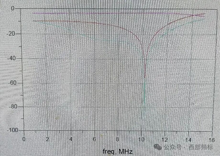
4. Frequency Response Characteristics
The operating frequency range of an LC power divider is determined by the values of its inductors and capacitors.
By optimizing the LC network order, designers can realize different filtering and frequency response characteristics.
Examples include:
- Second-order LC structures
- Third-order LC structures
- Multi-stage LC cascaded networks
An important advantage of LC power dividers is their integrated filtering capability.
Low-Pass LC Power Divider
A low-pass LC power divider suppresses high-frequency interference while distributing RF power.
High-Pass LC Power Divider
A high-pass LC power divider filters low-frequency noise and unwanted signals.
Because filtering and power distribution are integrated into one circuit, additional external filters are often unnecessary, simplifying RF system design.
Although single-stage LC power dividers usually have narrower bandwidth than broadband distributed dividers, multi-stage LC or RLC composite structures can significantly extend bandwidth performance.
Advantages of LC Power Divider
Compared with conventional microstrip power dividers, LC power dividers provide several important advantages.
Compact Size
Lumped-element components occupy much less PCB area than quarter-wave transmission lines, especially at lower frequencies.
Lower Cost
LC structures reduce PCB complexity and material usage, lowering overall production cost.
Easier Integration
LC power dividers are suitable for compact RF modules and integrated wireless systems.
Built-In Filtering Function
The LC network can simultaneously perform power division and frequency filtering.
Flexible Power Distribution Ratios
Different output power ratios can be realized by adjusting component parameters.
Typical Applications of LC Power Divider
LC power dividers are widely used in modern RF and microwave systems, including:
- Wireless communication systems
- 5G RF front-end modules
- IoT devices
- Signal distribution networks
- Radar systems
- Antenna feed networks
- RF testing equipment
- Satellite communication systems
Their compact structure makes them especially suitable for portable and space-constrained electronic products.
Conclusion
The LC power divider is an efficient and compact RF passive component that combines power distribution, impedance matching and filtering functions into a single lumped-element structure.
Compared with traditional distributed power dividers, LC power dividers offer:
- Smaller size
- Lower cost
- Better integration capability
- Flexible filtering characteristics
With the increasing demand for compact RF systems in wireless communication, IoT and radar technologies, LC power dividers continue to play an important role in modern microwave circuit design. ZR Hi-tech offers high-performance LC power dividers tailored for diverse RF and wireless communication applications, delivering reliable performance with optimized size and cost efficiency. Contact us to learn more.