Newsroom
How Does an RF Power Divider Work? Principle Explained
A power divider is a device that splits the energy of a single input signal into two or more outputs with equal or unequal energy, usually distributing energy equally. According to the number of outputs, it can be divided into two-way, four-way, six-way, eight-way, twelve-way, etc. It can also be used in reverse as a combiner.
It is often used in scenarios such as wireless communication, radar systems, satellite remote sensing, antenna arrays, and testing and measurement, mainly to achieve signal distribution, combining, and power balancing functions.

Power Divider’s Key Indicators
1. Frequency Range
This is the working premise of various RF/microwave circuits. The wider the frequency range, the broader the applicable scenarios, and likewise, the more difficult it is to design a power divider. The frequency range of a broadband power divider can cover ten or even dozens of octaves.
2. Distribution Loss
Refers to the amount by which the signal power decreases compared to the original input signal power after ideal power distribution. This value is theoretical. The calculation formula for ideal distribution loss (N is the number of output ports) is: Distribution Loss (dB) = 10 × log₁₀(1/N)
3. Insertion Loss
Insertion loss refers to the signal loss when a signal passes through a power splitter. When selecting an RF power splitter, products with low insertion loss should be chosen as much as possible, so the transmission quality will be better.
4. Isolation
Isolation can be measured using a network analyzer, directly measuring the loss between each output port. If the input power from each branch port can only be output from the main port and should not be output from other branches, this requires sufficient isolation between the branches.
5. VSWR
Input voltage standing wave ratio refers to the matching condition of the input port. The smaller the voltage standing wave ratio at each port, the better. The smaller the standing wave, the less energy is reflected.
For a passive power divider, its internal principle is to use a microstrip branch line to construct the branching network and utilize a quarter-wavelength microstrip transmission line for impedance matching, so that the impedance seen from each port is equal to 50 ohms, enabling energy transmission with maximum efficiency while dividing the signal. An active power divider is based on a passive power divider with an added amplification circuit, distributing the signal after amplification.
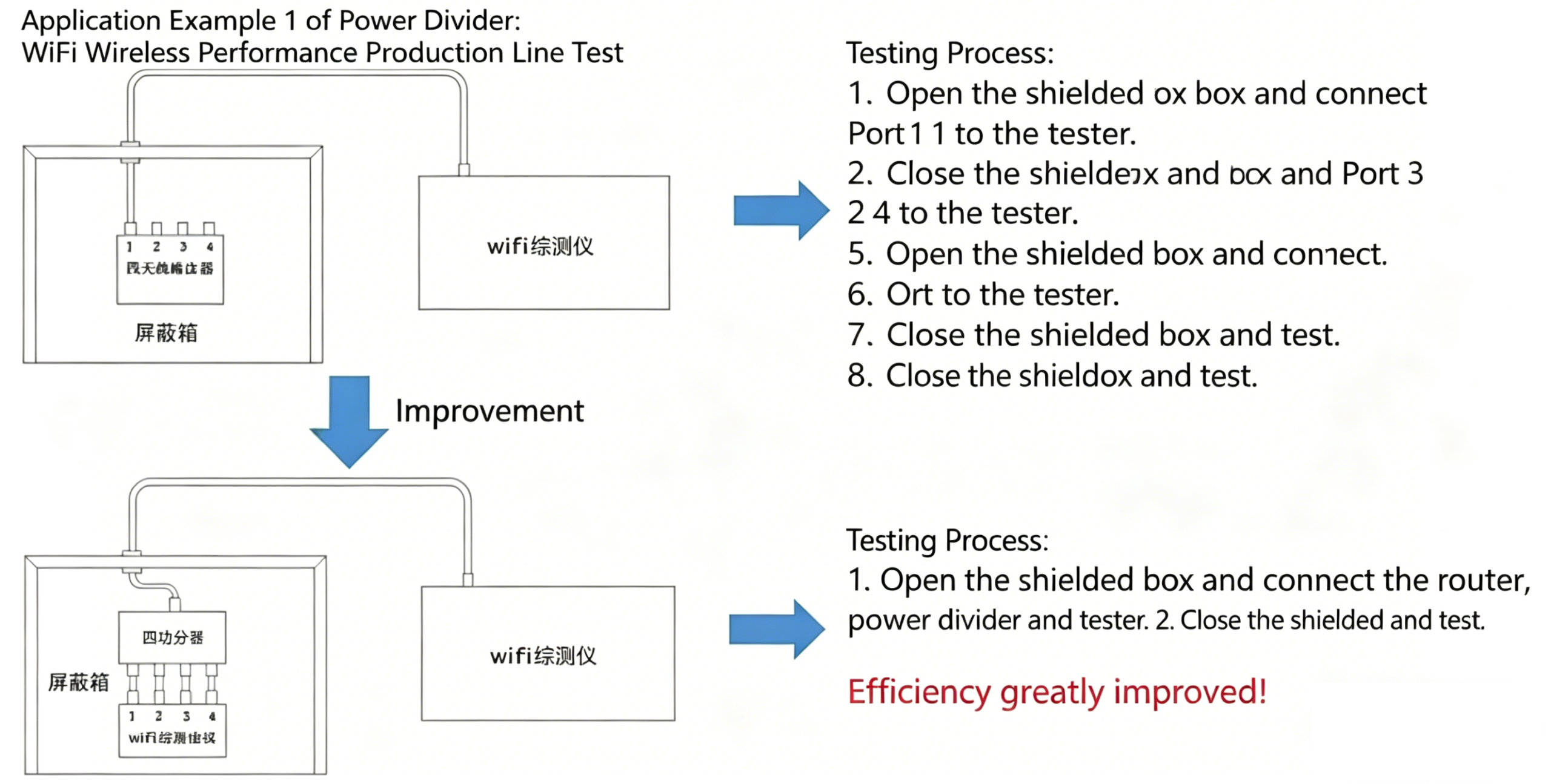
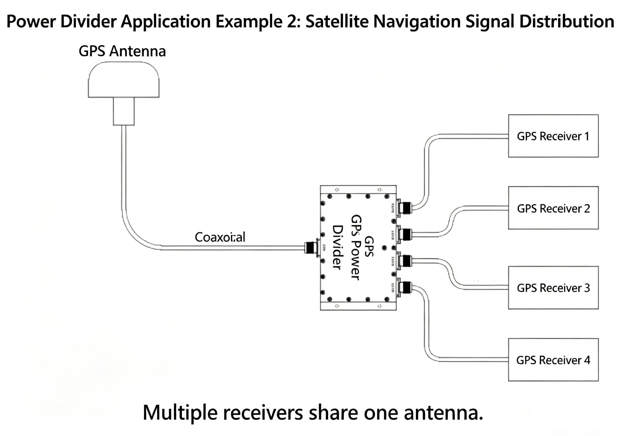
Power Divider Application
Below, let’s look at two real application case diagrams:
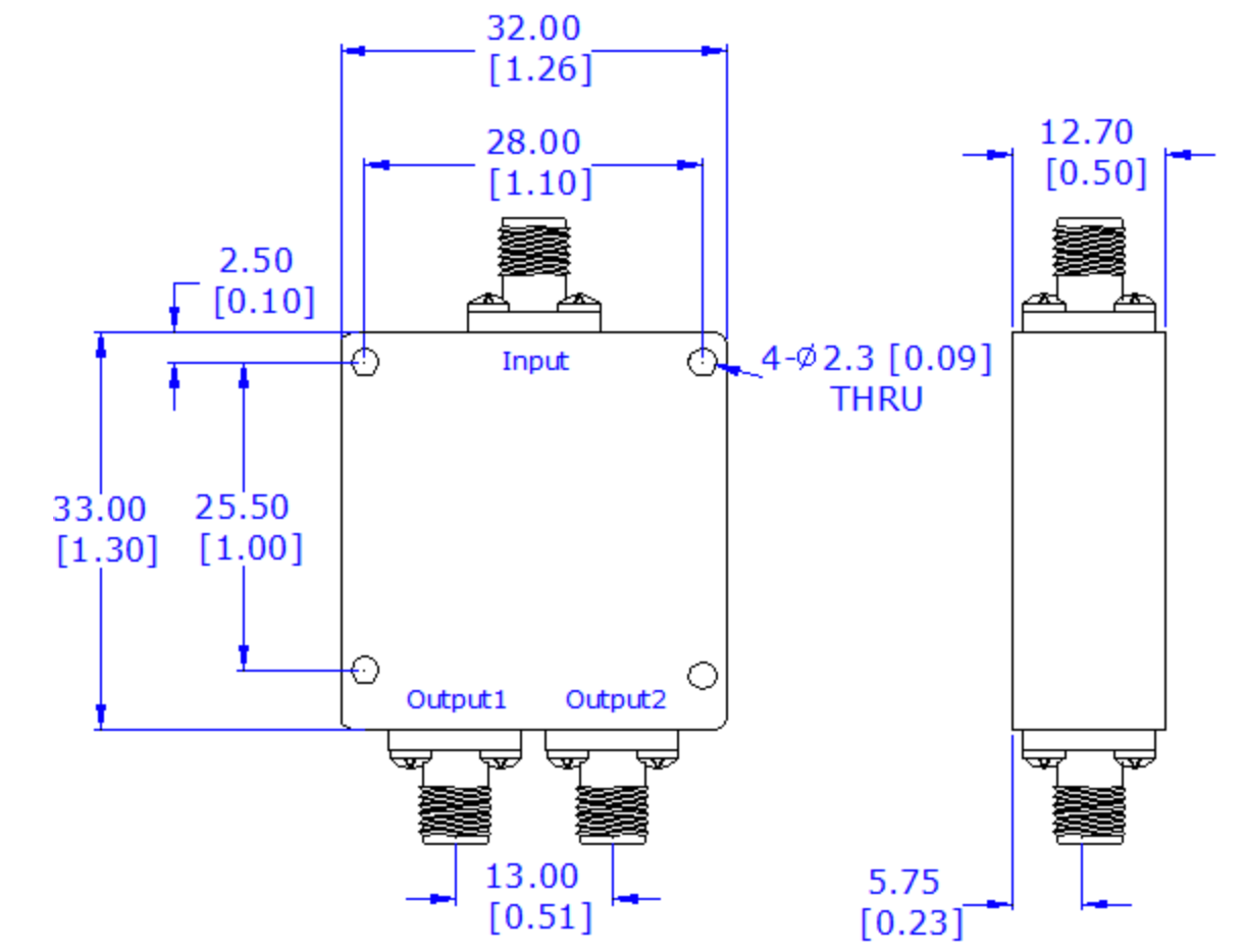
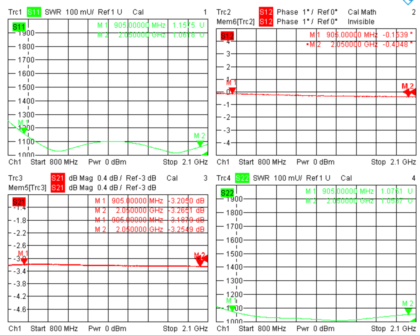
Below is a recommended new power divider from ZR Hi-tech:
0.905 to 2.05 GHz 2-way power divider