Newsroom
RF Fundamentals and Applications: A Comprehensive Guide
Radio frequency (RF) refers to electromagnetic waves in the frequency range of 30 MHz to 300 GHz. It is a core medium for wireless technologies and is widely used in wireless communications, weather monitoring, radar imaging, satellite transmission, and many other fields. Integrated circuits and modules developed using RF technology are embedded in a wide range of hardware and software products, including smartphones, satellite equipment, Bluetooth terminals, Wi-Fi devices, automotive electronics, radar systems, and consumer electronics. Electromagnetic waves are transverse waves that do not require a physical medium to propagate. They can travel efficiently through free space, including air and a vacuum, forming the fundamental basis of RF wireless transmission.
1 The Electromagnetic Spectrum
The electromagnetic spectrum encompasses all forms of electromagnetic radiation, ranging from low-frequency radio waves to high-energy gamma rays. It is commonly divided into seven categories: radio waves, microwaves, infrared, visible light, ultraviolet, X-rays, and gamma rays. All electromagnetic waves travel at the speed of light.
The RF spectrum is an important subset of the electromagnetic spectrum, extending from several megahertz to hundreds of gigahertz. Understanding its characteristics and application boundaries is essential for efficient spectrum allocation, wireless interference mitigation, and the optimized design of modern communication systems.
2 Fundamental Properties of Electromagnetic Waves
2.1 Frequency and Period
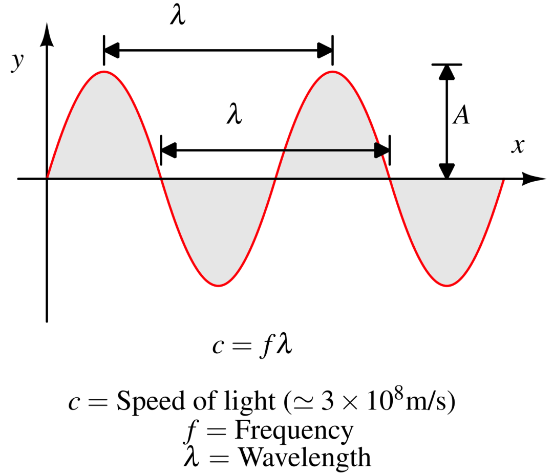
Frequency is the number of complete oscillation cycles an electromagnetic wave makes per second, measured in hertz (Hz). It is the key parameter describing how rapidly a wave oscillates. The period is the time required for one complete oscillation. It is the reciprocal of frequency, measured in seconds (s), and describes the time needed for a waveform to return to its initial state.
2.2 Wavelength
Wavelength is the physical distance between two consecutive wave peaks or troughs. It is represented by λ and measured in meters (m). The speed of light, frequency, and wavelength are related by the following equation: c = f × λ, where c is the speed of light, f is frequency, and λ is wavelength.
2.3 Amplitude
Amplitude is the maximum displacement of a wave from its equilibrium position and is usually represented by A. It is related to the strength of the electromagnetic field; for a given wave, a greater field amplitude corresponds to greater energy intensity. The units depend on the field quantity: electric-field amplitude is measured in V/m, while magnetic-field strength is commonly measured in A/m (magnetic flux density is measured in tesla, T).
2.4 Phase
Phase identifies the instantaneous position of a waveform within an oscillation cycle. It is measured in degrees (°) or radians (rad) and is a fundamental parameter in RF techniques such as modulation and signal synchronization.
3 Wireless Communication Principles and Transmission Challenges
3.1 Basic Principles of Wireless Communication
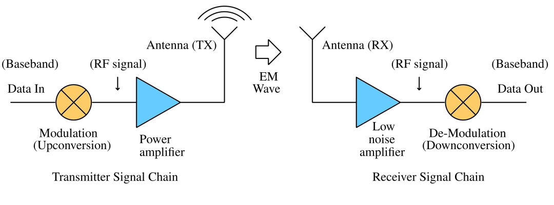
In wireless data transmission, the transmitter (TX) uses an antenna to convert an electrical signal into an electromagnetic wave. The signal travels through air or free space to the receiver (RX), where the receiving antenna converts the electromagnetic wave back into an electrical signal, enabling data exchange.
3.2 Key Challenges in Wireless Transmission
Compared with wired transmission, wireless channels operate in more complex environments. The main challenges include limited spectrum resources: wireless channels are shared by multiple users, spectrum is finite and costly, and transmission must comply with applicable regulations and spectrum-use rules. Significant signal attenuation: electromagnetic waves lose energy over medium and long distances, reducing signal strength and directly affecting range and communication quality. Dynamic channel conditions: movement of the transmitter or receiver, as well as changes in weather and obstacles, causes channel parameters to fluctuate over time and can reduce transmission stability.
4 Key RF Terms
4.1 Radio Frequency (RF)
In common industry usage, RF generally refers to electromagnetic waves at frequencies above 30 MHz. These frequencies can work with practical antenna sizes and can be transmitted efficiently through air and free space, making them central to wireless communications.
4.2 Carrier Signal
A carrier is a high-frequency oscillating signal used to carry information such as voice and data. Low-frequency baseband signals are not well suited to direct long-distance wireless transmission, so modulation is used to place the information onto a higher-frequency carrier. The carrier’s shorter wavelength makes practical antenna radiation possible. From antenna theory, effective aperture is proportional to the square of wavelength. For a fixed antenna gain, a shorter wavelength (higher frequency) generally allows a smaller antenna, which is a key principle behind antenna miniaturization in high-frequency RF equipment. The effective aperture of an ideal isotropic antenna is Ae = λ², while that of a half-wave dipole is approximately A = 0.13 × λ². Typical carrier frequencies and characteristics of common communication systems are listed below:
| Application | Carrier Frequency | Key Characteristics |
| AM radio broadcasting | 535 kHz–1605 kHz | Long transmission range; can diffract along the Earth’s curvature |
| FM radio broadcasting | 88 MHz–108 MHz | High audio fidelity; line-of-sight transmission and shorter range |
| 4G LTE / 5G (low bands) | 600 MHz–2.6 GHz | Good building penetration and broad coverage |
| Wi-Fi / Bluetooth | 2.4 GHz, 5 GHz | High data rates over relatively short distances |
| 5G millimeter wave | 24 GHz–53 GHz | Ultra-high-speed transmission; easily attenuated by walls and trees |
4.3 Baseband Signal
A baseband signal carries useful information such as voice, data, and video. In the RF signal chain, it is located after demodulation and downconversion but before the analog-to-digital converter (ADC) on the receive side, and after the digital-to-analog converter (DAC) but before modulation and upconversion on the transmit side.
4.4 Modulation
Modulation is a core RF communication technique in which the amplitude, frequency, or phase of a high-frequency carrier is varied to encode baseband information onto the carrier, allowing the signal to be transmitted through free space as an electromagnetic wave.
5 RF Power and Measurement Units
RF signal power spans an enormous range, from high-power signals at the transmitter to extremely weak signals at the receiver. Using a linear unit such as watts can make comparisons and calculations cumbersome across this range, so logarithmic units are widely used to express RF signal parameters.
5.1 Decibel (dB)
The decibel is a dimensionless logarithmic unit used to express the relative ratio between quantities such as power or voltage. It simplifies the measurement and comparison of signal parameters that span a very wide range.
5.2 dBm (Absolute Power Unit)
dBm is a standard absolute unit for measuring RF signal power, referenced to 1 milliwatt (mW). For power ratios, the conversion factor is 10; for voltage ratios under the same impedance, it is 20. For example, 0 dBm = 1 mW and 10 mW = 10 dBm. A power level of −110 dBm is approximately 10⁻¹⁴ W = 10⁻⁵ nW; signals at this level can easily be masked by environmental noise.
5.3 dBc (Relative Power Unit)
dBc expresses power relative to a carrier and is a relative measurement. It is used to quantify the power of noise, harmonics, spurious signals, and other interference components compared with the main carrier, complementing the absolute unit dBm.
5.4 Attenuation and Gain
Attenuation is the loss of signal power as a signal travels through cables, air, walls, or other media. It is measured in dB and is an inherent feature of wireless transmission. Gain is the increase in signal power provided by components such as amplifiers or directional antennas. Also measured in dB, gain can compensate for transmission losses.
5.5 Example: Bluetooth Signal Transmission Loss
Consider a 2.4 GHz Bluetooth link with a transmit power of 30 dBm (1 W), a transmission distance of 100 m, half-wave dipole antennas at both ends, and a received power of −45 dBm. Link loss = transmit power − received power = 30 dBm − (−45 dBm) = 75 dB. This corresponds to a power reduction of more than 31 million times, illustrating the substantial losses that can occur in wireless transmission.
5.6 Converting Between Power and Voltage
A standard reference load impedance in RF systems is 50 Ω, allowing power and voltage to be converted using the load impedance. With a 50 Ω load, −110 dBm corresponds to an RMS voltage of approximately 0.7 μV, a very weak signal that can easily be overwhelmed by noise.
6 Operating Modes of RF Communication Systems
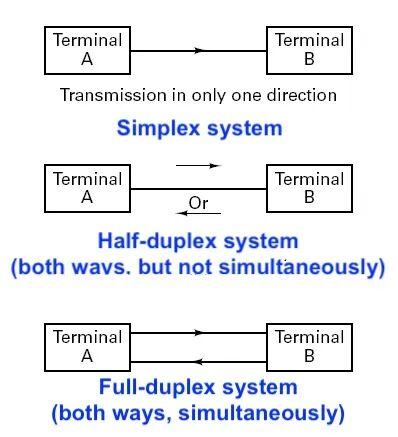
6.1 Simplex Systems
A simplex system supports one-way data transmission. Device roles are fixed: one end only transmits, while the other only receives, and the receiver cannot send feedback over the same channel. This mode avoids collisions and channel contention and can offer high reliability. A typical example is the RF system used in remote car keyless-entry systems.
6.2 Half-Duplex Systems
A half-duplex system supports two-way communication but cannot transmit and receive simultaneously. Devices alternate between transmit (TX) and receive (RX) modes, with a short switching delay. Because the system uses a single frequency channel, it can use spectrum efficiently in lower-bandwidth applications. Wi-Fi and Bluetooth are common examples. Devices can switch TX/RX states rapidly at the physical layer, making the interaction appear simultaneous to users even though the operation is half-duplex. This approach can support high-data-rate applications such as HD video calls.
6.3 Full-Duplex Systems
A full-duplex system transmits and receives signals simultaneously without alternating operating modes. It often uses separate frequency channels to isolate the transmit and receive signals, providing high transmission efficiency and low latency. Examples include cellular mobile communications and satellite communication systems.
7 Core Hardware Components of an RF System
A complete RF system consists of a transmit chain (TX) and a receive chain (RX). Specialized components work together to convert signals bidirectionally between electrical signals and electromagnetic waves. The main building blocks are outlined below:
7.1 Core Transceiver Chips and Modules
Key transmit-side components include a digital-to-analog converter (DAC), IQ mixer/modulator, power amplifier (PA), local oscillator (VCO + PLL), and a high-stability reference crystal oscillator. Key receive-side components include a low-noise amplifier (LNA), IQ demodulating mixer, intermediate-frequency (IF) amplifier, RF filter, and analog-to-digital converter (ADC).
7.2 Balun
A balun is an RF signal-conversion component that converts between balanced differential signals and unbalanced single-ended signals. In the transmit chain, it can convert a differential mixer output into a single-ended signal suitable for a power amplifier input. In the receive chain, it can convert the LNA’s single-ended output into a differential signal for the demodulation circuit.
7.3 Matching Network
A matching network, sometimes called an impedance transformer, matches impedances between components, such as a power amplifier and an antenna. This helps maximize power transfer and minimize signal reflections. Impedance mismatch can cause excessive voltage, abnormal current, damage to RF components, and reduced transmission efficiency.
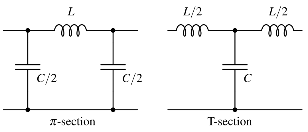
7.4 Filters
Filters are key RF components for interference mitigation. They suppress noise, reject unwanted signals, and limit bandwidth to meet spectrum requirements while selecting the desired communication channel. Common types include low-pass filters and high-Q band-pass filters, which can improve receiver sensitivity and transmission stability.
7.5 Antennas
An antenna is an RF energy-conversion transducer and the interface between a wireless system and free space. On the transmit side, it converts a guided electrical signal into an electromagnetic wave radiated into free space. On the receive side, it converts an incoming electromagnetic wave into an electrical signal.
8 Key RF Transmission Parameters and Loss Models
8.1 Phase Noise
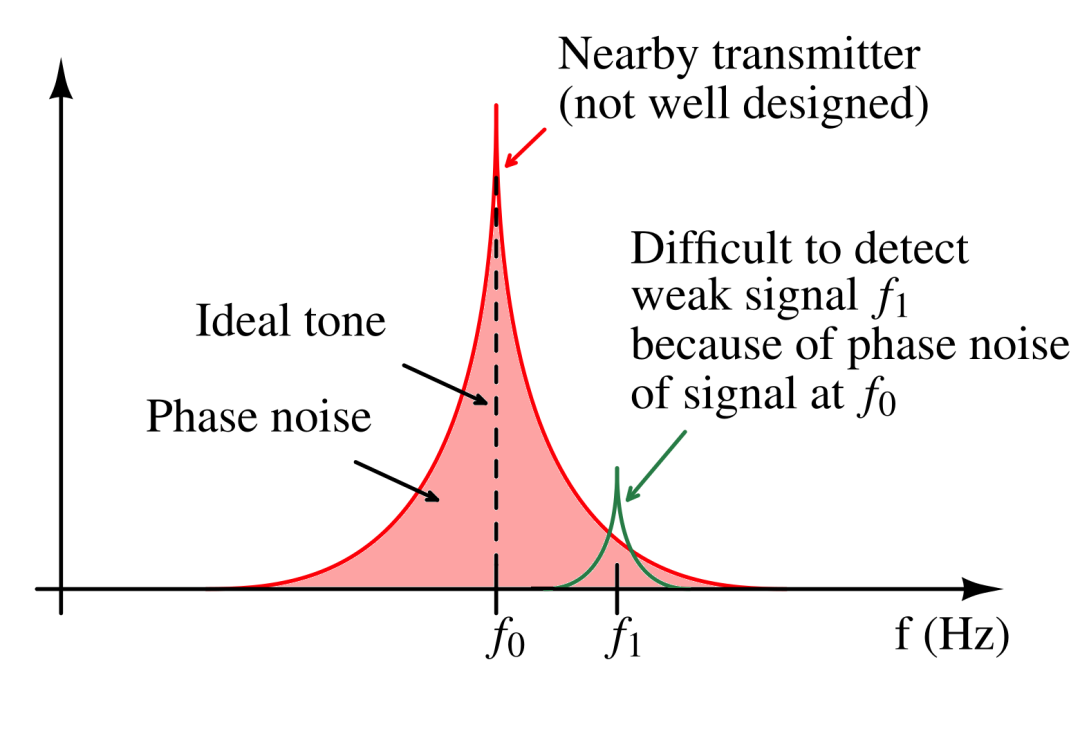
Phase noise is a key performance parameter of RF transceivers. Phase noise generated by the local oscillator can mask weak signals at nearby frequencies, making it difficult for the system to identify the desired signal accurately and significantly degrading receiver sensitivity and communication quality.
8.2 Friis Transmission Equation
The Friis transmission equation is used to estimate received power in free-space wireless transmission and is a fundamental tool for RF link-budget calculations. It can be expressed in linear or logarithmic form to suit different calculation needs. Higher received power generally improves the signal-to-noise ratio (SNR) and supports better receiver sensitivity. In decibel form:
8.3 Free-Space Path Loss (FSPL)
As an electromagnetic wave spreads through free space, its power density decreases with distance. This loss can be quantified using the free-space path-loss equation, which applies to ideal line-of-sight conditions without obstructions or multipath fading. In decibel form: A key rule of thumb is that doubling frequency increases free-space path loss by about 6 dB at the same distance; under otherwise comparable conditions, a 6 dB improvement in link budget can approximately double the range. Lower-frequency RF signals, such as 433 MHz, can generally travel farther than higher-frequency signals such as 868 MHz under comparable conditions.
8.4 Ways to Improve RF Transmission Range
Three common approaches can improve the effective range of an RF system: increase transmit output power using an external power amplifier (PA), improve receiver sensitivity using a low-noise amplifier (LNA), and use a high-gain directional antenna.
9 Comparison of Parameters for Common RF Applications
Operating frequency, wavelength, and suitable antenna size vary significantly across wireless applications. The following table lists representative parameters for half-wave dipole antennas:
| Application | Operating Frequency | Wavelength | Half-Wave Dipole Antenna Length |
| FM radio broadcasting | 88–108 MHz | 2.8–3.4 m | 75 cm |
| Bluetooth | 2.4 GHz | 12.5 cm | 3.1 cm |
| Wi-Fi (2.4 GHz band) | 2.4 GHz | 12.5 cm | 3.1 cm |
| Wi-Fi (5 GHz band) | 5 GHz | 6 cm | 1.5 cm |
| GSM cellular network | 900 MHz | 33 cm | 8.25 cm |
| GNSS (GPS) | 1.575 GHz | 19 cm | 4.75 cm |
10 Satellite Communication Frequency Bands
Satellite communications use several standardized frequency bands. Each band has different uplink and downlink frequencies, bandwidths, application areas, and propagation characteristics. Representative parameters are listed below:
| Band | Downlink Frequency (GHz) | Uplink Frequency (GHz) | Typical Bandwidth (MHz) | Characteristics |
| L band | 0.9–1.6 | 0.9–1.6 | 15 | Shared with terrestrial services; relatively good penetration |
| S band | 1.61–1.63 | 2.48–2.50 | 70 | Shared ISM (industrial, scientific, and medical) band |
| C band | 3.7–4.2 | 5.925–6.425 | 500 | Shared with terrestrial services; widely used |
| X band | 7.25–7.75 | 7.9–8.4 | 500 | Often used for military and government communications |
| Ku band | 11.75–12.2 | 14.0–14.5 | 500 | Subject to rain attenuation |
| Ka band | 17.7–21.2 | 27.5–31.0 | 3500 | Very wide bandwidth; significant rain attenuation |