
Newsroom
How Compact Directional Couplers Improve Reliability in Satellite Communication Systems
In the microwave and millimeter-wave communication field, high-power monitoring, high-frequency transmission, and miniaturized integration have always been major industry challenges. Traditional directional couplers often struggle to balance these requirements. Some designs suffer from poor directivity, which reduces measurement accuracy. Others have fragile structures that cannot handle high-power applications. Meanwhile, larger designs are difficult to integrate into compact RF systems.
However, a recent study published in Electronics provides a solution to this long-standing challenge. It introduces a compact high-directivity reverse directional coupler designed specifically for high-frequency and high-power scenarios.
In this article, we will explore how this innovative design works and how it is changing the way engineers approach RF signal monitoring and system integration.
Industry Pain Point: The ‘Dilemma’ of Directional Couplers in High-Frequency Scenarios
Whether it’s Ku-band satellite uplinks, radar transmitters, or industrial microwave equipment, you can’t do without a directional coupler — it’s like a “signal monitor,” responsible for separating forward and reverse power while protecting detectors from being damaged by high power. But traditional designs always have shortcomings:
- Poor directivity: the difference in even and odd mode phase velocities in microstrip parallel coupled lines leads to insufficient directivity in low-coupling scenarios, making detection data inaccurate;
- Can’t handle high power: to compensate for directivity, traditional designs often use small capacitors and narrow line structures, which can overheat and burn out when current is concentrated;
- Too bulky: multi-section coupling and broadband designs can improve performance but make the size unwieldy, preventing integration into compact devices.
And this new design just happens to hit all three pain points perfectly!
Core Innovation: 3 key Designs That Balance Being ‘small, strong, and precise’
1. Topology Reconstruction: Replace Traditional Coupling Lines with Ring Networks and Say Goodbye to ‘fragile structures’
Traditional designs always focus on ‘compensating for even-odd mode differences,’ which actually complicates the structure. This coupler takes a different approach, based on a ‘ring four-port network’ (as shown in Figure2), replacing the originally isolated transmission lines with parallel coupled lines that have even-odd mode differences.
![Figure 2. Equivalent circuit of: (a) the original general ring-type four-port with lumped-distributedelements [33); (b) the original even- and odd-mode two-port equivalent circuit; (c) the modifiedgeneral ring-type four-port with lumped-distributed elements [33]; (d) the modified even- andodd-mode two-port equivalent circuit.](https://www.zrhitech.com/wp-content/uploads/2026/06/微信图片_2026-06-26_153320_181.png)
2. Super Compact: 60° Electrical Length Design, achieving a Tiny 4mm×5.5mm Size
Traditional coupled lines usually use a λ/4 (90°) electrical length, which makes it hard to reduce their size. This design boldly opts for a 60° electrical length for the coupled line, and pairs it with an inner and outer stub combination layout (as shown in Figure 5). In the end, the active area is only 4mm×5.5mm—smaller than similar products, yet it can still maintain a 20dB weak coupling performance.
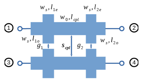
What does this compactness mean? It can easily fit into satellite communication modules and small radar devices, without needing to enlarge the system to accommodate the coupler, greatly improving the flexibility of equipment integration.
3. Accurate and Efficient: Peak 45dB Directional, Detection Data Doesn’t Go Off Track
Directivity is the key indicator for a coupler — the higher the number, the better it separates forward and reverse power, and the more accurate the measurement. This coupler has a minimum directivity of 20dB and a peak of up to 45dB in the 12.8-14.8GHz range (Ku-band satellite uplink frequencies), as shown in the test results in Figure 10.
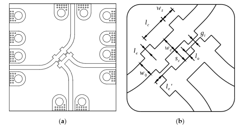
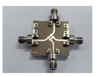
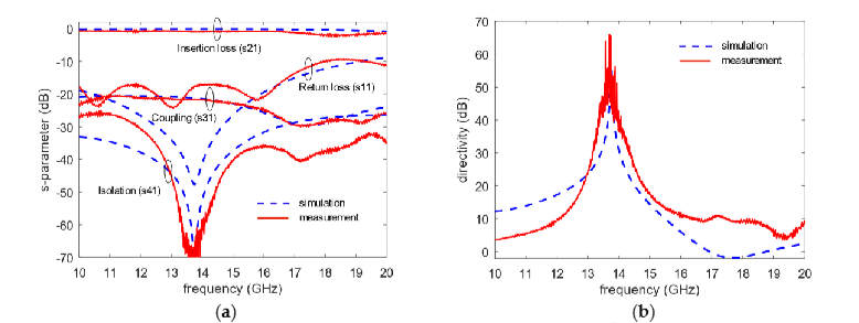
This means that even if the load impedance varies, it won’t affect the accuracy of power detection, making the signal data for satellite communication and radar monitoring more reliable and reducing transmission errors.
Practical Applications: Not just Satellite Communication, These Scenarios Can All Use It
The innovative design of this coupler allows it to really shine in several high-frequency, high-power scenarios:
- Satellite Communication: It works with the Ku-band uplink (14-14.5GHz).It accurately monitors transmission power. This ensures stable signal transfer. It also prevents communication interruptions caused by power fluctuations.
- Radar Systems: In high-power transmission scenarios, it protects the detector from damage while precisely reporting power status, improving radar detection accuracy.
- Industrial Microwave Equipment: In high-power devices like microwave heating and plasma processing, it enables real-time power monitoring to keep equipment running safely.
- 5G Millimeter-Wave Base Stations: Its compact design fits the dense integration needs of base stations, and high directionality ensures signal transmission without interference, enhancing communication quality.
Tech Insight: A ‘No Compromise’ Design Philosophy
The success of this coupler lies in the fact that it didn’t take the old route of ‘sacrificing A for B.’ Instead, through topological innovation, size optimization, and precise modeling, it achieves a balance of ‘directivity, power matching, and size.’
- Instead of compensating, just ‘make use’: Skip complex compensation structures. Directly leverage the even-mode and odd-mode properties of coupled lines. This approach simplifies the overall design process. It also improves circuit stability.
- Don’t blindly chase wide bandwidth, focus on what you actually need: most high-power systems only need to work in specific frequency bands. So ditch redundant wideband designs for smaller size and lower loss;
- Model the entire chain: from circuit topology to physical dimensions, derive complete design equations without endless trial and error, making mass production easier.
Conclusion
Microwave and millimeter-wave technologies keep advancing. The market urgently needs RF components with better performance, smaller form factors and higher reliability. Compact directional couplers with high directivity solve key pain points. They fit high-power signal monitoring, high-frequency transmission and miniaturized system design perfectly. These couplers deliver multiple core strengths. They feature high directivity, precise measurement, compact layout and outstanding high-power tolerance. Thus they play a vital role in many fields. Typical scenarios include satellite communications, 5G base stations, radar equipment and future wireless systems.
ZR Hi-Tech focuses on high-performance RF and microwave component R&D and production. Our product lineup covers directional couplers, power dividers, RF amplifiers, SAW filters and custom RF parts. We fully cater to changing demands from worldwide communication sectors. We supply both off-the-shelf standard RF components and tailor-made designs. Our custom services cover unique frequency and power specifications. Our professional engineering team delivers stable, feasible technical solutions. Reach out to ZR Hi-Tech now. Let our RF technology empower your next-gen projects.



