Newsroom
Directivity-induced Measurement Uncertainty of Directional Couplers
In our previous article, Directional Coupler RF Power Measurement Errors: Causes and Analysis, we examined how the finite directivity of a directional coupler can introduce measurement uncertainties. These uncertainties become especially important when measuring reflected power in RF systems.
We explored the relationships among directivity, return loss, leakage signals, and phase differences. The analysis showed how each of these factors can affect RF power measurement accuracy.
While the theoretical discussion helps explain the source of measurement errors, RF engineers often need practical guidance for real-world applications. For example, how much uncertainty should be expected when measuring a load with 30 dB return loss? What directivity is required to achieve a specific measurement accuracy? How does measurement error change as return loss increases?
In this article, we answer these questions through practical examples. We calculate return loss measurement uncertainty under different directivity conditions. We also examine how return loss and coupler directivity influence measurement accuracy. In addition, we compare the directivity requirements for reflected-power and forward-power measurements.
Finally, we introduce a practical method for measuring directional coupler directivity in the laboratory. Understanding these examples can help engineers select the right directional coupler and improve the accuracy of RF, microwave, and millimeter-wave measurement systems.
Calculating The Uncertainty of Measuring Echo Loss
To clarify the discussion above, let’s tackle an example problem from Rohde & Schwarz’s basic documentation on vector network analyzers (VNA). In this example, we aim to measure a load with an actual return loss (RL) of 30 dB using a coupler with 40 dB directivity (D). What are the maximum and minimum values of the measured return loss?
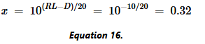
From the third figure above, we know the difference between the ideal signal power and the non-ideal signal power is D – RL = 40 – 30 = 10 dB. So, from the calculation below, the amplitude of the non-ideal voltage is 0.32 times that of the ideal voltage:
By plugging this value of x into equation 15, we can see that the overall voltage can be: 1.32 times higher than the actual value (x = 1.32), or 0.68 times lower than the actual value (1 – x = 0.68). Therefore, the measured power could be: 2.4 dB higher than the actual value (20log(1.32)), or 3.35 dB lower than the actual value (20log(0.68)).
The measured reflected power is related to the return loss of the load. The higher the reflected power, the lower the return loss. When the measured reflected power is 2.4 dB higher than the actual value, the measured return loss is 2.4 dB lower than the actual value. This leads to:
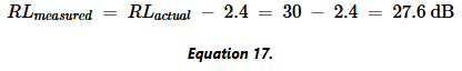
Similarly, when the measured reflected power is 3.35 dB lower than the actual value, the measured return loss is 30 + 3.35 = 33.35 dB. Therefore, the measured return loss could be any value between 27.6 dB and 33.35 dB.
Calculating The Uncertainty of Measured Echo Loss
To become more familiar with these calculations, let’s consider another example. Suppose we use a directional coupler with a directivity of 35 dB to measure a load whose actual return loss is 20 dB. We can follow the same procedure used in the previous example. The first step is to determine how much smaller the amplitude of the non-ideal voltage is compared with the ideal voltage.
Using the equations derived earlier, we obtain:
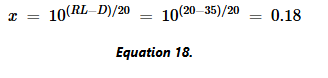
The overall voltage can be: 1.18 times higher than the actual value, which is 1 + 0.18. Or 0.82 times lower than the actual value, which is 1 – 0.18. So, the measured power can be: 1.44 dB higher than the actual value, which is 20log(1.18), or 1.72 dB lower than the actual value, which is 20log(0.82).
How Do Return Loss and Directivity Affect Errors in Directional Couplers?
The picture below shows the errors in measured reflected power under different echo loss and directivity values.
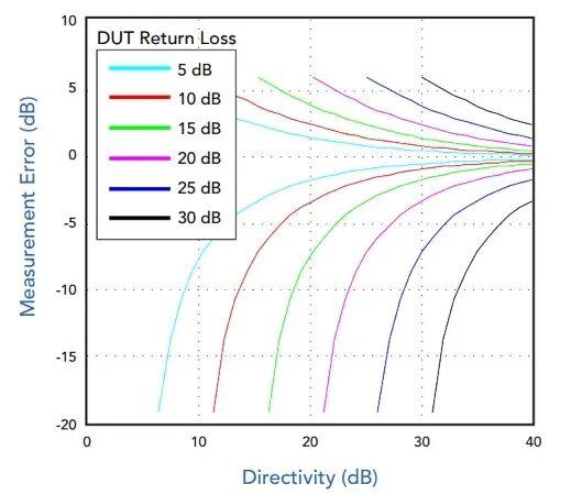
First, measurement errors rise with higher return loss. Given fixed input power Pi, unwanted leakage power remains unchanged. Meanwhile, the valid reflected signal Pr declines. This amplifies relative measurement errors.
Measuring The Forward Power of Directional Couplers
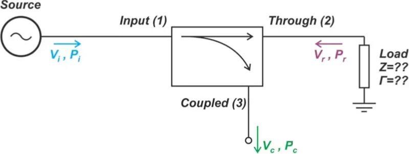
We can also use a directional coupler to sample the forward power, like in the diagram.
Compared to measuring reflected power, the directional requirements for a coupler in forward power measurement are more relaxed. This is because the input power being measured (Pi) is greater than the reflected power (Pr). Figure 7 shows the forward power measurement errors for different return loss and directivity values.
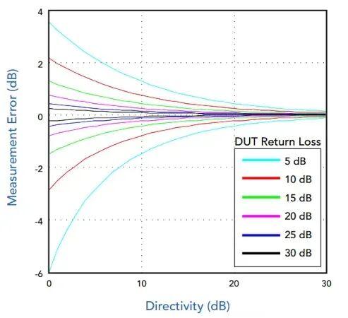
Please note that when the load return loss is low, the error increases. This is because a lower return loss means more power is being reflected back to the source. In turn, this causes the coupler’s output to have larger unwanted signals. However, even with a very small return loss, a directivity of 15 dB can still ensure that the error in forward measurements doesn’t exceed about 1 dB.
Measuring The Directivity of Directional Couplers
Finally, since this is closely related to the error analysis provided in this article, I want to mention a practical method for measuring the directionality of a coupler. We usually can’t measure this directionality directly because the forward and reverse waves produce comparable signal components at the coupler’s output.
However, we can indirectly measure the directionality of the coupler by modifying Figure 1 and using a sliding load, as shown in the figure.
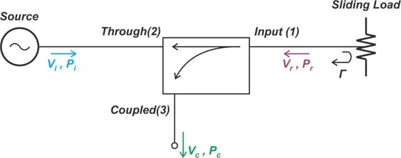
Changing the position of the sliding load introduces a variable phase shift in the reflected signal. From the discussion above, we know that when we change the position of the sliding load, the voltage at the coupled port traces a circular pattern. By finding the minimum and maximum power levels at the coupled port, we can determine the directionality of the coupler.
Conclusion
This article further explores measurement uncertainties caused by the finite directivity of directional couplers, with practical calculation examples illustrating how return loss and coupler directivity jointly affect the accuracy of reflected power measurements. As return loss rises, relative measurement errors tend to increase, while higher directivity effectively suppresses signal leakage and improves test reliability. We also verified that forward power measurement has looser requirements for coupler directivity compared with reflected power testing.
Following industry practical guidelines, selecting a directional coupler with directivity 15 dB higher than the DUT return loss can restrict measurement errors within 1 dB, which serves as a valuable reference for component selection in real RF, microwave and millimeter-wave systems. Additionally, we introduced a laboratory method using a sliding load to indirectly measure coupler directivity, completing the full workflow from error analysis to practical testing.
A solid understanding of these principles helps engineers properly configure test setups, choose suitable directional couplers, and minimize measurement deviations. For professional solutions, technical support and product consultation related to RF and microwave components, please feel free to contact ZR Hi-tech.