
Newsroom
Complete Guide to 1-to-3 RF Power Divider Performance Comparison
In microwave circuits, RF power dividers are essential components used to split signals into two or more proportional output paths. When operated in reverse, they can also function as power combiners. Therefore, they are commonly referred to as power dividers/combiners. RF Power Divider Performance is critical in microwave and millimeter-wave systems because it directly affects signal transmission efficiency, insertion loss, isolation, bandwidth, and overall system stability.
Power dividers are widely used in array antenna feed networks, microwave communication systems, radar systems, and solid-state power amplifiers. In antenna arrays, a power divider distributes one signal into multiple outputs. In microwave solid-state amplifiers, it combines several signals into a single higher-power output signal. As a key microwave component in solid-state transmitters, the design quality of a power divider directly impacts transmitter efficiency and amplitude-frequency performance.
The design methods of multi-way power dividers are generally divided into two categories. The first method uses a single structure to divide one input signal directly into multiple outputs. The second method uses multiple one-to-two power divider units connected in cascade to achieve multi-way power division. In this approach, the one-to-two divider serves as the basic building block for creating N-way equal power dividers.
For odd-way power dividers, a common design method is to terminate one output path with a matching load. However, introducing a load may reduce certain performance parameters. As a result, researchers have explored different structures for odd-way power dividers. In this work, three types of one-to-three RF power dividers were designed and simulated, and their advantages and disadvantages were systematically compared.
Direct 1-to-3 Equal Power Divider
Generally, a power divider that splits a signal into multiple outputs using a single structure provides higher power distribution efficiency. Because the signal passes through fewer stages, the insertion loss is usually lower.
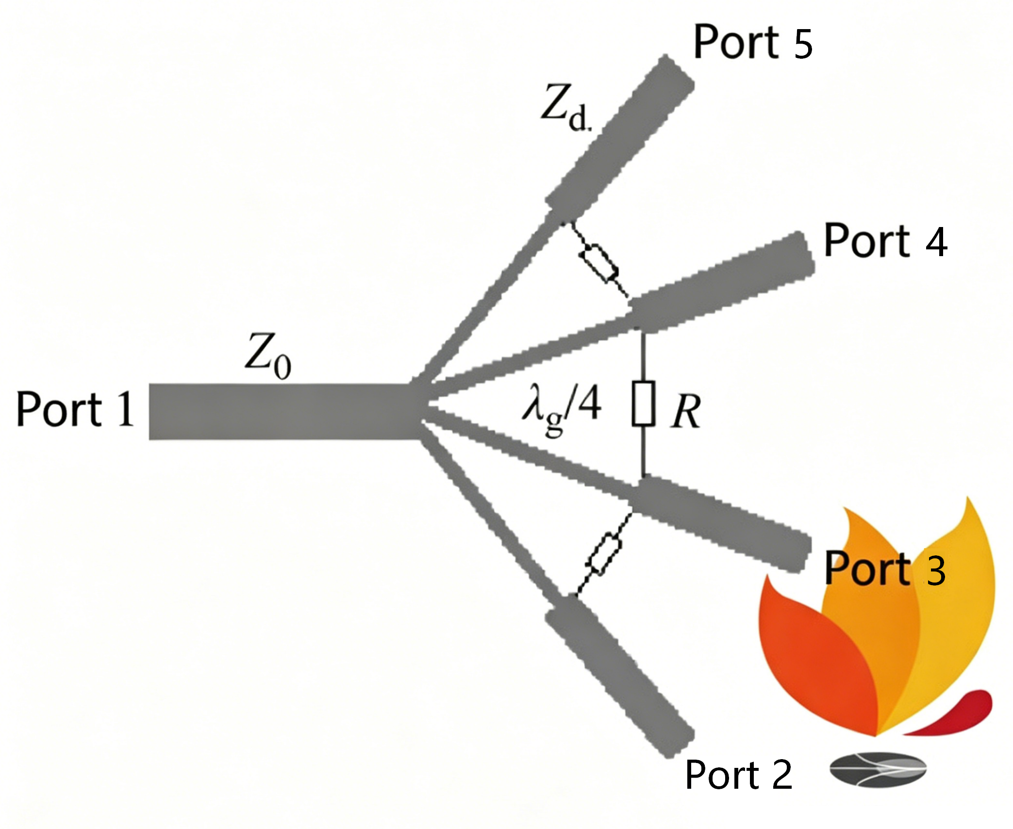
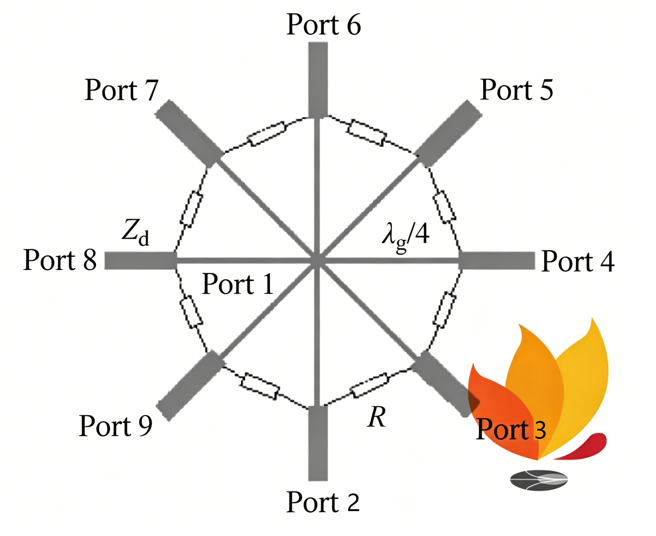
When the number of output paths is greater than two, microstrip one-to-multiple power dividers are commonly divided into two main types: fan-shaped power dividers and radial power dividers, as shown in Figures 1 and 2.
Each structure has different application characteristics. In a fan-shaped power divider, electromagnetic waves propagate along a planar structure, and different output ports can be designed to provide different power distribution ratios.
Design of the Basic Unit 1-to-2 Power Divider
The second type of power divider splits a single signal into multiple outputs step by step through a series of one-to-two structures, with its most basic unit being a one-to-two power divider. To ensure good isolation at each output port, the one-to-two power divider uses a Wilkinson power divider.
The symmetry of the Wilkinson power divider ensures signal balance and isolation, and the isolation resistor further improves the isolation of the output ports. A single-section 3 dB Wilkinson power divider can achieve bandwidth doubling. By changing the characteristic impedance of the two output branch lines, power distribution with any desired ratio can be realized.
There are three key indicators for describing a 3 dB Wilkinson power divider: voltage standing wave ratio (VSWR), insertion loss, and isolation. Due to symmetry, the insertion loss between ports 1 and 3 is equal to that between ports 1 and 2. When designing a power divider, one should consider: that the VSWR within the operating frequency band is as close to 1 as possible, the insertion loss is as close to 3 dB as possible, and the absolute value of isolation is as large as possible; for a one-to-many power divider, the phase consistency between ports should also be considered.
Three-way Power Divider with Load Matching and Their Performance
An N-way equal power divider can be formed by cascading multiple Wilkinson power divider circuits. The schematic diagram of an N-way cascaded Wilkinson power divider is shown in the figure.
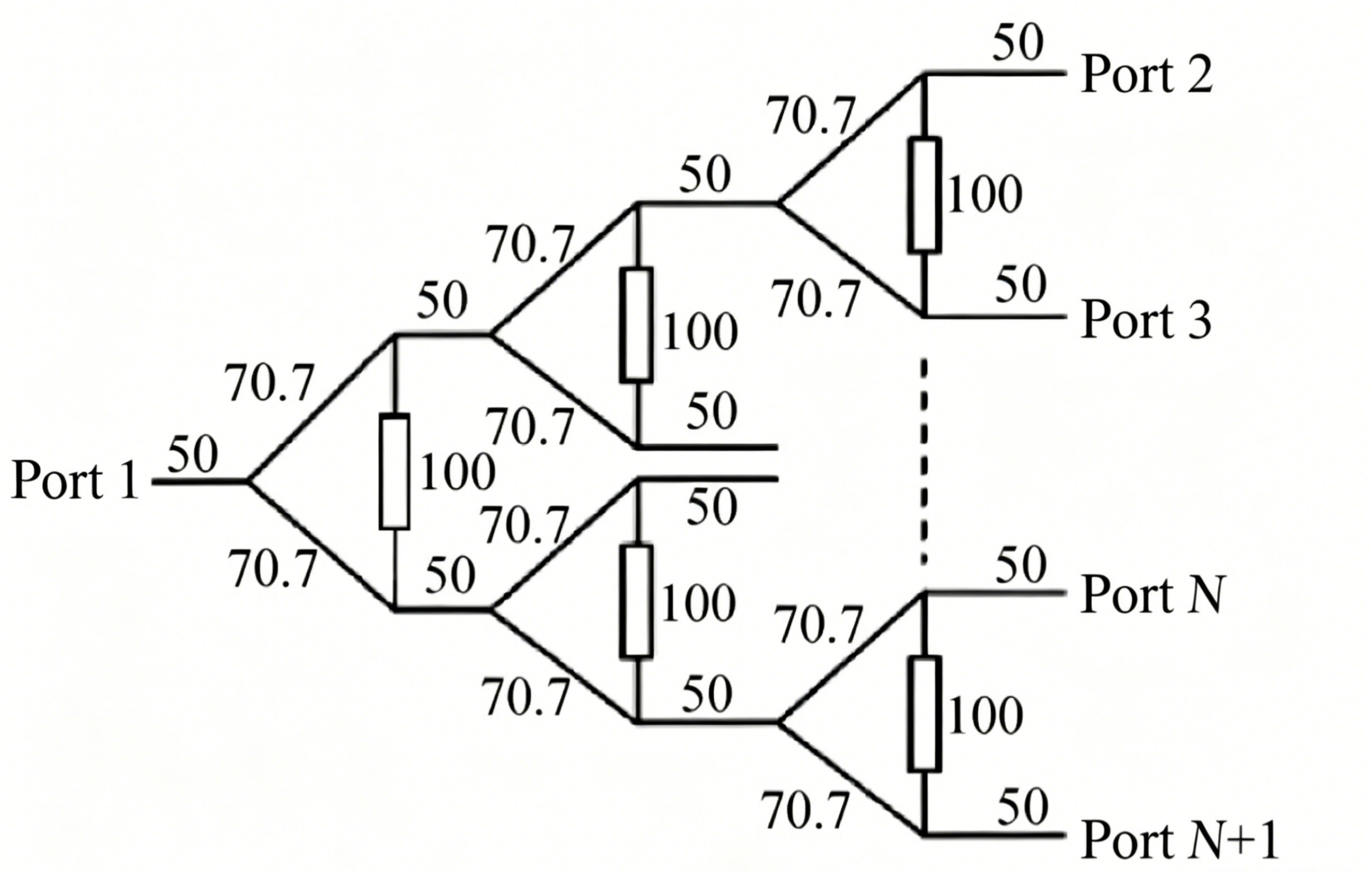
For odd-numbered power dividers, the usual design method is to add a load match to one of the paths. Three 3 dB Wilkinson power dividers are cascaded to form a 1-to-4 power divider, and a 1-to-3 power divider is designed by choosing one path of the 1-to-4 power divider for load matching. The simulation model and port settings are shown in the figure.
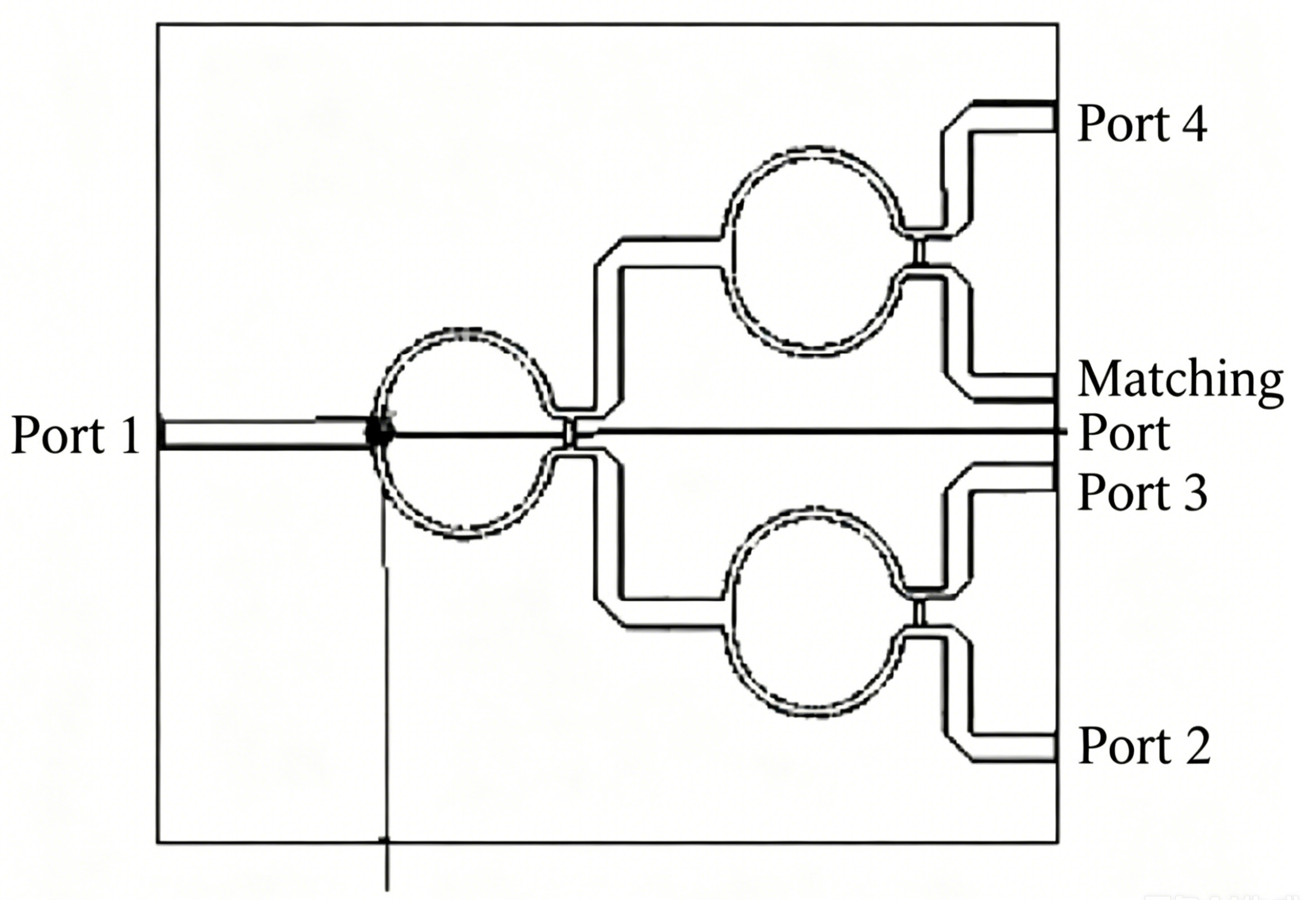
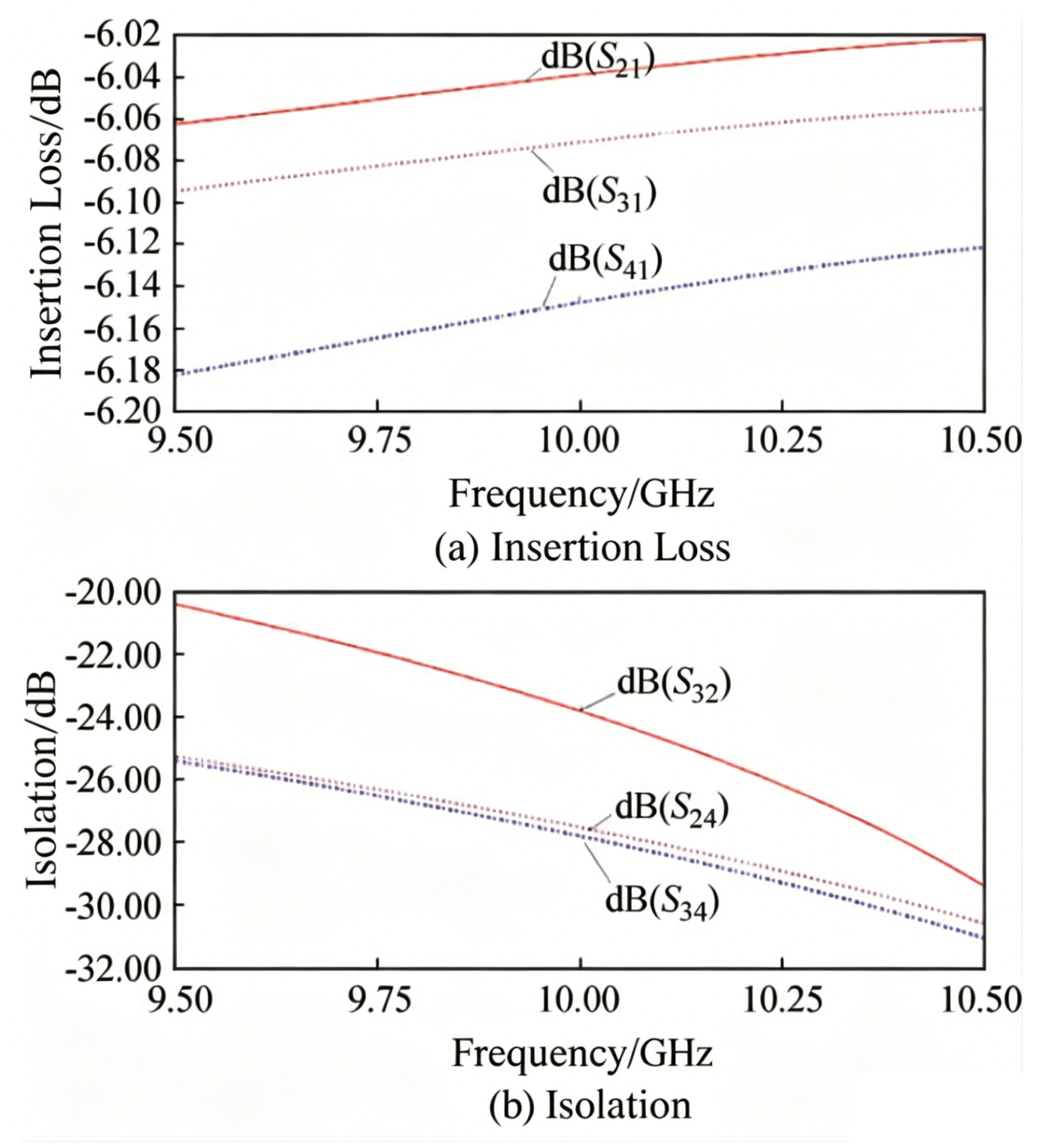
The simulation results of the channel insertion loss and isolation between channels are shown in the figures. The simulation results of this power splitter are: VSWR less than 1.25, phase difference less than 0.5°, maximum insertion loss of -6.1 dB, and minimum isolation of -23 dB. Under ideal conditions, the insertion loss of a one-to-four power splitter is -6 dB; adding load matching causes energy loss, and the simulation results are close to the theoretical value. The isolation between the channels of this power splitter is relatively good.
A one-to-three Power Divider Formed by Cascading Two one-to-two Power Dividers
In planar microwave integrated circuits, simple multi-way power dividers often cannot provide sufficient isolation between output ports. Although power dividers with load matching can improve isolation, they usually introduce higher insertion loss.
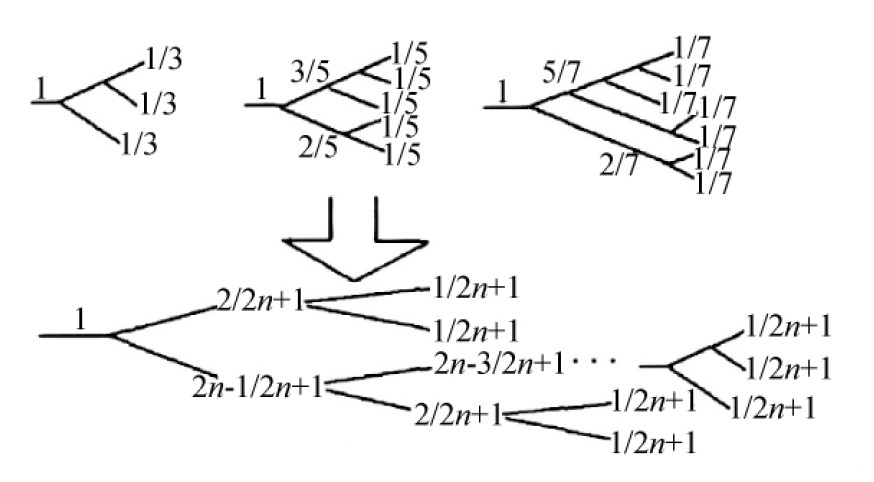
Another common design method is to build a 1-to-3 equal power divider by cascading an unequal 1-to-2 power divider with an equal 1-to-2 power divider. In this structure, the input signal (P_0) is first divided unequally in a 1:2 ratio. The branch carrying (2P_0/3) of the power is then equally divided into two outputs.
Using this design concept, larger odd-way power dividers such as 1-to-5 and 1-to-7 structures can also be developed.
Figure shows the structure of a 1-to-3 power divider. In the circuit:
- (Z_0) represents the characteristic impedance of the branch line between the input and output transmission lines.
- (Z_1), (Z_2), (Z_3), and (Z_4) represent the characteristic impedances of different branch line sections.
- (Z_{01}) and (Z_{02}) are the characteristic impedances of the two equal output branches.
- (R_1) and (R_2) are the isolation resistor values used to improve output port isolation.
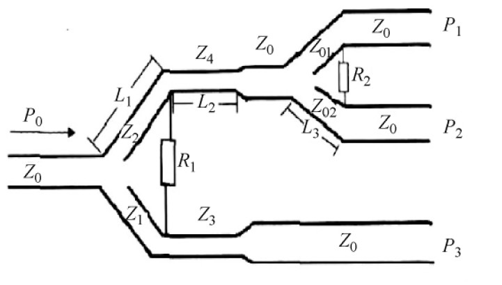
Power divider simulation results: the port standing wave is less than 1.45, the phase difference is less than 0.5°, the maximum insertion loss is -4.9 dB, the minimum isolation is -17.4 dB, and the simulated insertion loss is close to the theoretical value. From the simulation results, it can be seen that the isolation of a 1-to-3 power divider designed by cascading an unequal 1-to-2 power divider with an equal 1-to-2 power divider is better than that of a fan-type direct 1-to-3 power divider.
Comparison of the Simulation Performance of Three Types of Structural Power Divider
The standing wave performance of power divider can be improved by optimizing impedance matching. The main performance comparison of different power divider structures usually focuses on three parameters: insertion loss, isolation, and phase consistency.
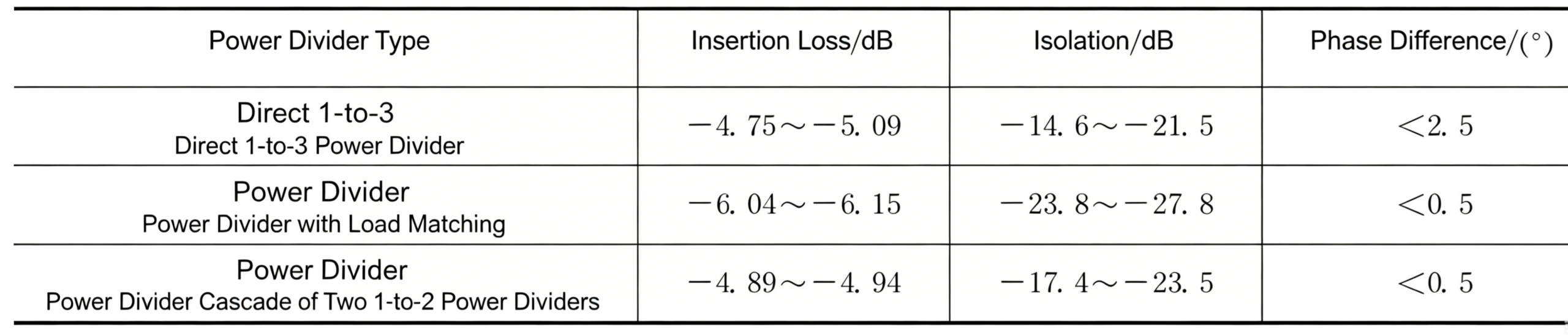
Table 1 summarizes the simulation results of three different one-to-three power divider structures. The comparison includes insertion loss, isolation performance, and phase consistency. Based on the analysis of the simulation data, the following conclusions can be drawn.
a) Fan-Shaped Direct 1-to-3 Power Divider
The fan-shaped direct one-to-three power divider has a compact structure and relatively low insertion loss. However, one output path shows poor isolation performance. Compared with the other two structures, the phase consistency between output ports is also slightly worse.
b) Cascaded Wilkinson 1-to-3 Power Divider
A one-to-three power divider constructed by cascading three 3 dB Wilkinson power dividers provides high isolation and excellent phase consistency between ports. However, because one branch is connected to a matching load that absorbs part of the signal power, the insertion loss is relatively high.
When operating at very high frequencies, especially above the K-band, the load-connected branch may affect the amplitude and phase consistency of the other output ports. In this case, the position of the matching load should be carefully optimized to reduce its impact.
c) Cascaded Unequal-Split and Equal-Split Power Divider
A one-to-three power divider designed by cascading an unequal-split one-to-two divider with an equal-split one-to-two divider offers several advantages. It provides low insertion loss, good power distribution consistency, and excellent phase consistency. Its isolation performance is moderate and falls between the other two structures.
Conclusion
Different one-to-three equal power divider structures offer different electrical characteristics and application advantages. Through HFSS simulation and performance comparison, it can be seen that each design method has its own strengths and limitations.
The fan-shaped direct one-to-three power divider features a compact structure and low insertion loss, making it suitable for applications with strict size requirements. However, its isolation performance is relatively poor. The cascaded Wilkinson power divider provides excellent port isolation and phase consistency, but its insertion loss is higher because part of the signal power is consumed by the matching load. In contrast, the cascaded unequal-split and equal-split one-to-two power divider achieves a balanced overall performance, offering low insertion loss, good phase consistency, and moderate isolation performance.
Therefore, when selecting an RF power divider, engineers should comprehensively consider factors such as insertion loss, isolation, phase consistency, operating frequency, physical size, and system requirements to choose the most suitable design solution for their applications.
As a professional manufacturer of RF and microwave components, ZR Hi-Tech provides high-performance RF power dividers, Wilkinson power dividers, cavity power dividers, couplers, filters, and customized microwave solutions for global communication industries. With strong R&D capability and strict quality control, ZR Hi-Tech is committed to delivering reliable RF solutions for 5G communication systems, radar, satellite communication, antenna feed networks, and RF testing applications.
If you are looking for customized RF power divider solutions or professional microwave components, feel free to contact ZR Hi-Tech for technical support and product recommendations.



