Newsroom
Broadband Reflectionless Power Divider Based on LTCC: Design, Simulation and Application
As wireless communication technologies continue to advance, RF front-end systems demand greater integration, broader bandwidth, and improved return loss characteristics. Conventional filter and power divider combinations are typically implemented as separate components. This approach often increases insertion loss, occupies more circuit space, and produces unwanted stopband reflections. These reflections can degrade overall system performance and even impact upstream devices. Therefore, developing an integrated solution that provides both broadband operation and reflectionless performance has become an important research direction in modern RF and microwave design.
Recently, a research team from Xi’an proposed an integrated design method for a wideband out-of-band reflectionless filter power divider based on LTCC (Low Temperature Co-Fired Ceramic) technology, successfully overcoming the aforementioned design bottlenecks. The related results were published, providing a new feasible solution for the integration and miniaturization of RF front-end devices.
Core Design: Trinity Structure, Achieving Functional Synergy
The key innovation of this filter power divider is its highly integrated design. It combines three essential functions: bandpass filtering, power division, and out-of-band absorption. Traditional RF designs typically achieve these functions using multiple cascaded components. In contrast, this integrated structure performs all three functions within a single circuit. This enables better performance optimization, reduced insertion loss, and a more compact implementation.
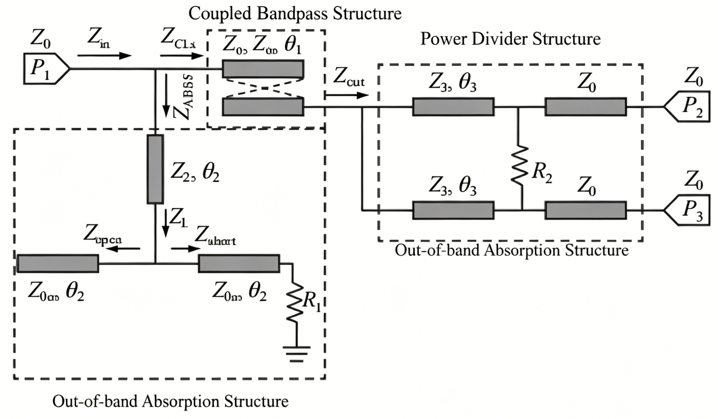
Coupled Band-Pass Structure
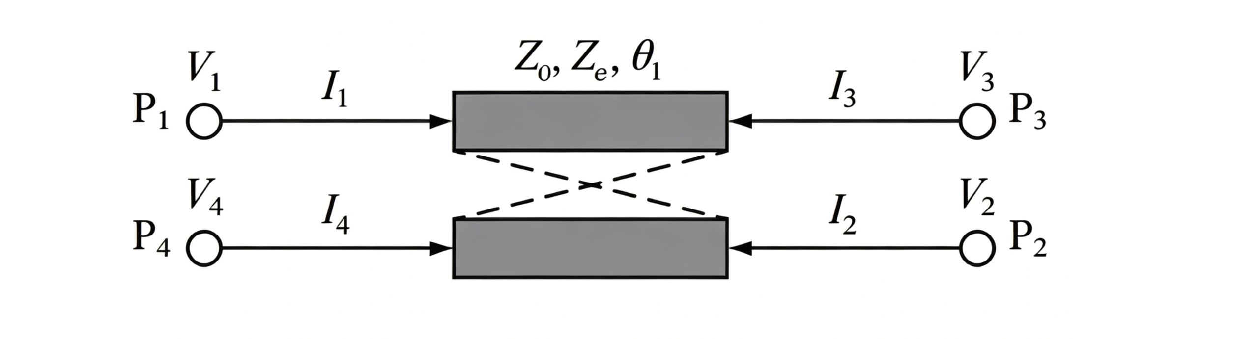
Using a strongly coupled quarter-wavelength coupled transmission line, the passband bandwidth is widened by increasing the coupling coefficient K — the larger the coupling coefficient, the wider the relative bandwidth (FBW). When Ze=165Ω and Zo=70Ω, the coupling coefficient K=0.4, achieving a relative bandwidth of 77.2%, laying a foundation for wideband signal transmission.
Out-of-band absorber structure
The integrated band-stop filter with a 50Ω absorbing resistor, through precise impedance matching design, allows out-of-band signal energy to be efficiently dissipated by the absorbing resistor, avoiding echo reflections, and fundamentally solves the problems of traditional filtered power dividers where stopband reflections cause damage to front-end RF devices and reduce system linearity.
Power Distribution Structure
Seamlessly integrates with the coupled bandpass structure, ensuring that signals within the passband are output in-phase and with equal amplitude from the dual output ports, while also achieving good isolation between the output ports.
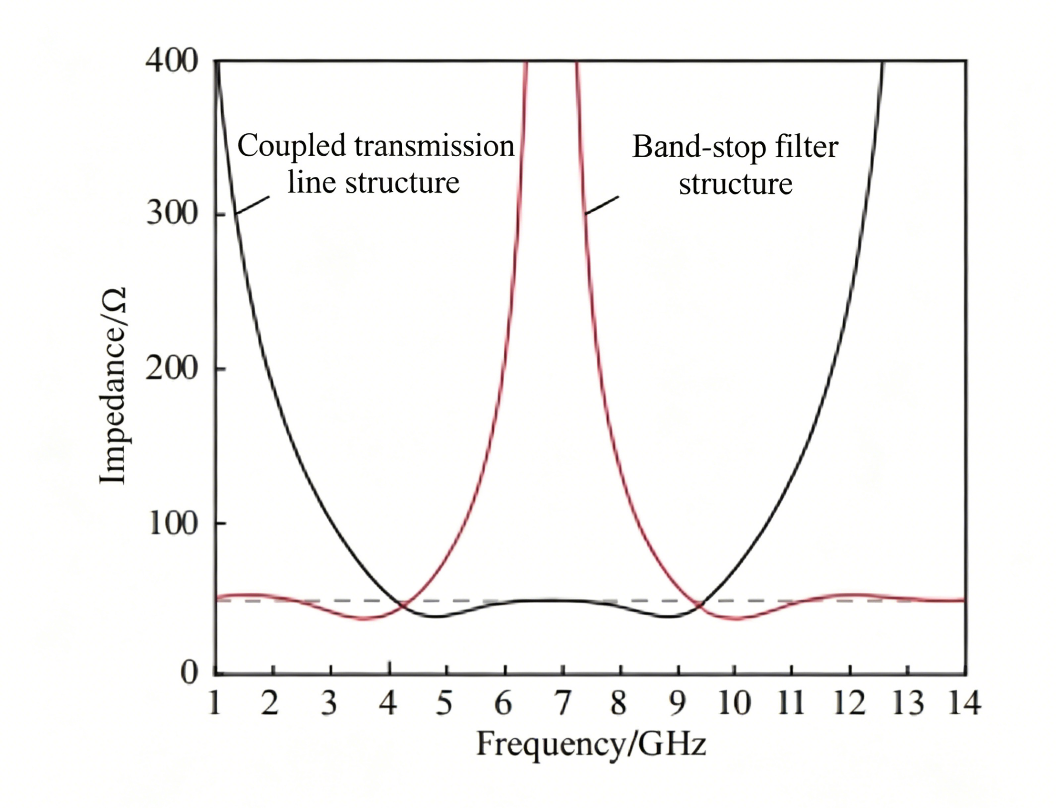
The reflectionless operation is based on intelligent impedance switching between the passband and stopband regions. During normal operation, the coupled bandpass structure provides a matched 50 Ω path, allowing signals to pass efficiently to the power divider outputs. The absorptive branch remains effectively isolated.
When signals fall outside the desired frequency band, the impedance characteristics change automatically. The bandpass path becomes highly resistive, while the absorptive network presents a 50 Ω matched load. Unwanted signals are therefore absorbed by the resistor instead of being reflected back to the source.
This unique impedance-control mechanism enables low-reflection operation, protects upstream RF components, and improves overall system stability.
Simulation Verification: Excellent Performance, Parameters Meet Standards
To verify the feasibility of the design theory, the research team, based on HFSS full-wave simulation software, transformed the theoretical circuit into an actual LTCC microstrip structure for simulation validation, with the device process and structural design both aligned with engineering practice:
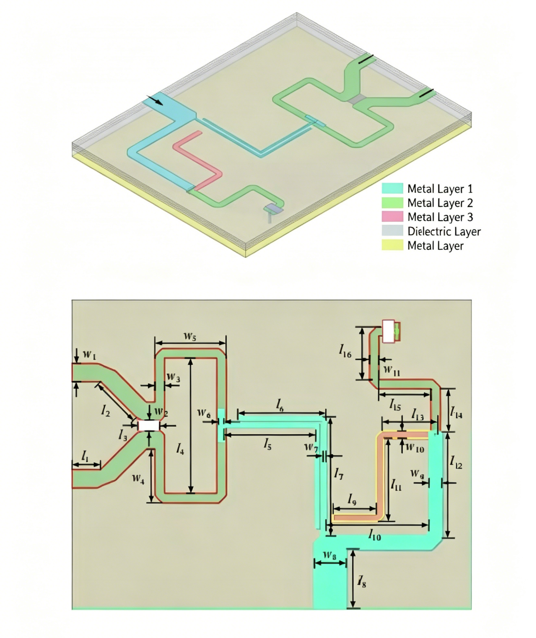
LTCC process parameters
Using a 6-layer dielectric and 4-layer metal design, the ceramic dielectric is Ferro A6M (dielectric constant 5.9, loss tangent 0.0011), and the metal layers are made of highly stable gold. The layers are connected through metallized vias, and the overall physical dimensions are only 11mm × 8.5mm × 0.582mm, meeting the miniaturization requirements of RF devices.
Core Performance Indicators
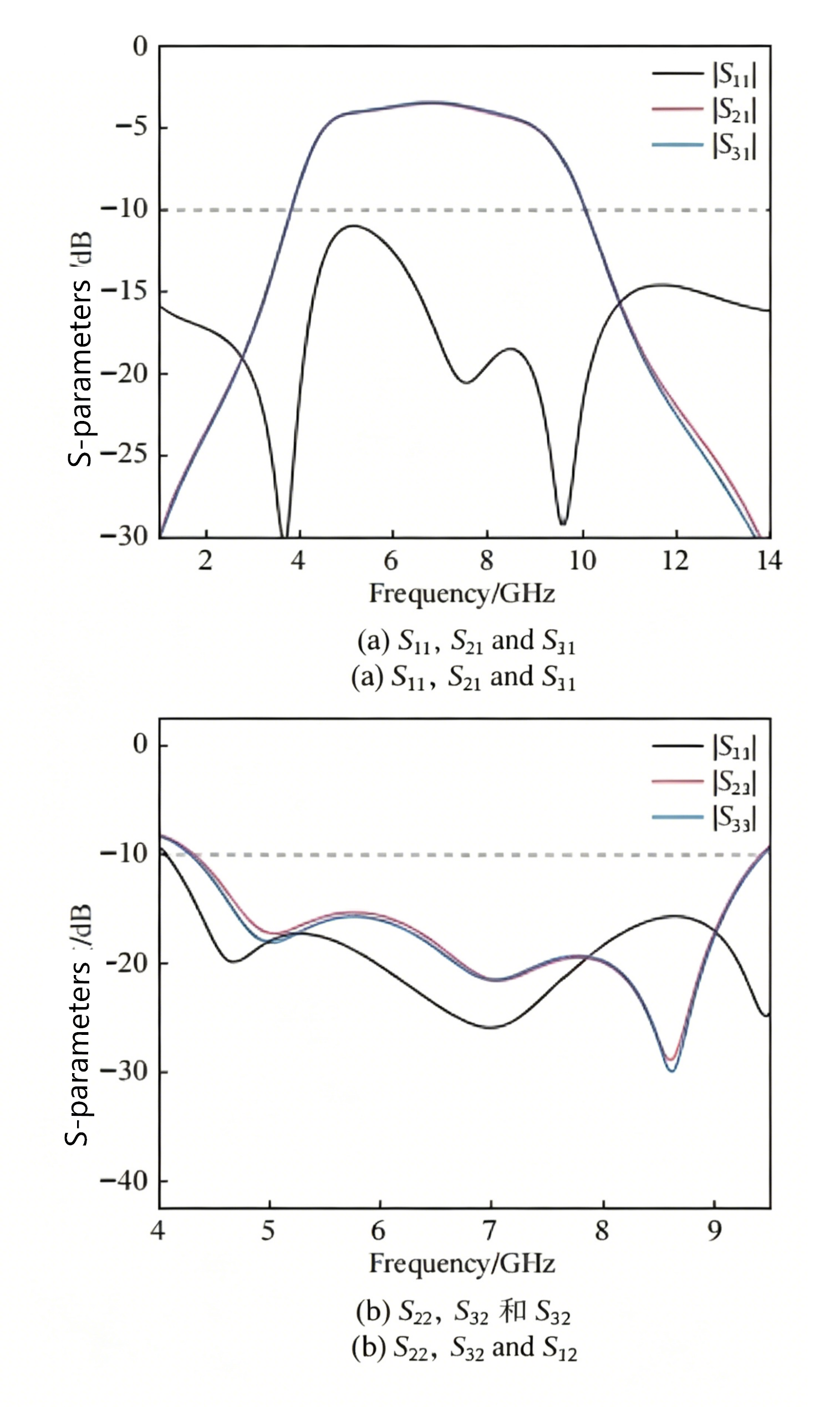
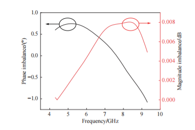
Simulation results confirm the filtered power divider works at a center frequency of 6.85 GHz. Its −6 dB fractional bandwidth reaches 74%, covering the frequency range from 4.3 GHz to 9.4 GHz. For in-band performance, the divider features 3 dB equal power split. Its insertion loss stays as low as 0.4 dB and 0.5 dB for the two output paths. The input out-of-band return loss S11 exceeds −15 dB, while the absorptive resistor achieves 95% power absorption efficiency. On the output side, output reflection is better than −15 dB and port isolation surpasses 15 dB. The two outputs have a phase imbalance within ±1° and amplitude mismatch no more than 0.01 dB. Such performance realizes nearly ideal equal-amplitude and in-phase power divider.
In addition, surface current simulation analysis further verified the design mechanism: within the passband, current flows from the input port through the coupled transmission line and power divider structure directly to the output port, with no energy loss in the absorbing resistor; outside the passband, all current flows through the out-of-band absorbing structure and is completely absorbed by the resistor, producing no reflected energy, which is in high agreement with the theoretical design.
Performance Comparison: Combines Multiple Advantages, Suitable for Engineering Applications
Built on LTCC integrated fabrication, the component features a compact size and satisfies miniaturization demands for modern RF front-end modules. Meanwhile, the research team mentions one existing drawback: its out-of-band rejection rolls off slowly. Future work can focus on optimizing stopband suppression, which guides further development of high-performance RF passive components.
Application Value: Empower RF Front-end, Adapt to Integrated Development
As a new process in modern integrated circuit design, LTCC technology combines the characteristics of high integration, small size, and high stability. The proposed integrated design of filtering and power division integrates the three major functions of filtering, power division, and non-reflection into a single LTCC device, effectively solving the insertion loss, size, and reflection problems of traditional discrete solutions.
This design scheme can be directly applied to RF front-end transceiver systems in fields such as satellite communication, 5G/6G communication, and microwave microsystems, significantly improving the communication quality, reliability, and integration of the system. It provides new design ideas and engineering references for the design of RF devices in wireless communication systems, and has important practical application value and promotion significance.
Conclusion
Driven by the ongoing trend toward highly integrated, wideband, low-loss and reflection-free RF components, the LTCC-based reflectionless filter power divider delivers a feasible engineering solution to break common design limitations for microwave circuit designers.
As verified above, the proposed divider achieves a 73.5% fractional bandwidth alongside zero out-of-band reflection, low insertion loss of 3.5 dB and over 15 dB port isolation. It also maintains excellent amplitude and phase consistency and reduces footprint effectively via LTCC miniaturized integration. These outstanding characteristics make it well suited for modern compact RF front-end applications.
Future research can focus on improving out-of-band rejection slope and expanding to multi-band topologies. After continuous performance optimization, such integrated reflectionless power dividers will evolve into essential passive building blocks and facilitate the upgrade of next-generation miniaturized wireless communication systems.
ZR Hi-tech keeps optimizing LTCC power divider solutions to meet diverse wideband RF engineering demands. Contact us to support your innovative programs.