
Newsroom
RF Couplers: The ‘Invisible Bridge’ Behind Wireless Communication, Understand Its Core P...
An RF coupler is an essential passive component in RF circuits. It transfers RF signals between circuits or devices. It handles core tasks such as directional signal sampling, power distribution, interference isolation, and impedance matching. In short, it acts as a “traffic hub” for signals, ensuring efficient and stable signal flow with low interference and loss.
How It Works: The ‘Magic’ of Electromagnetic Fields
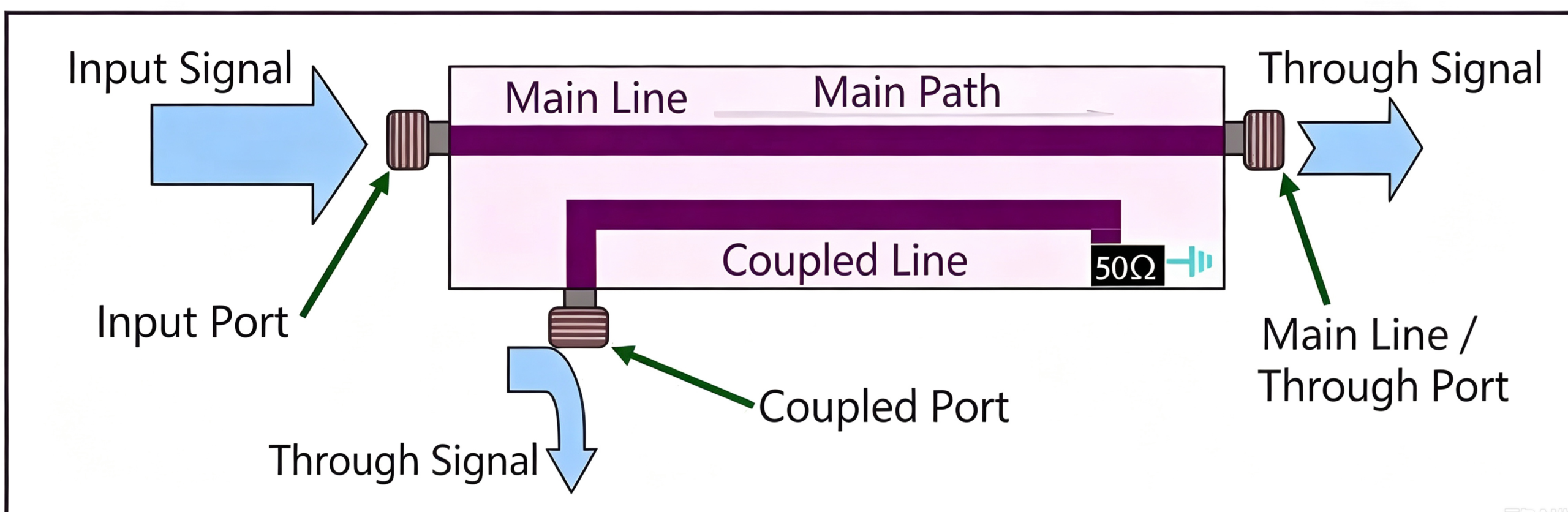
The working principle of an RF coupler is based on electromagnetic coupling. When a signal passes through the coupler, part of the energy is coupled from the main transmission line to another port. This effect is achieved through capacitance, inductance or magnetic effects, and allows signal splitting or monitoring.
Coupling behavior depends on two main physical effects:
1.Near-field coupling effect:
When the main transmission line is powered, it generates an alternating electromagnetic field, and the adjacent coupled line acts like an ‘induction coil’ that captures energy.
2.Transmission Line Theory:
Control coupling accuracy through microstrip/ coaxial line structure design:
- Strong coupling: the smaller the spacing between lines, the greater the coupling energy.
- Directivity: asymmetric structure design isolates reverse signals.
Key Tech Metrics: Performance ‘Checkup Report’
The capability of an RF coupler is defined by six main parameters (using a directional coupler as an example)
| Parameter | Definition | Ideal Value | Engineering Significance |
|---|---|---|---|
| Coupling (C) | Ratio of input power to coupled-port power | 10 dB / 20 dB / 30 dB, etc. | Determines the signal sampling ratio |
| Directivity (D) | Difference between coupling and isolation, D = |I − C| | >20 dB | Higher directivity means stronger interference rejection |
| Isolation (I) | Ratio of input power to isolated-port power | >30 dB | Prevents reverse signal leakage |
| Insertion Loss (IL) | Power attenuation when the mainline signal passes through | <0.5 dB | Lower insertion loss has less impact on the main signal |
| Frequency Range | Operating bandwidth within which the specified parameters are met | e.g., 0.1–40 GHz | Supports compatibility across multiple frequency bands |
| Power Handling | Maximum input power that the device can handle | 50 W–3 kW | A key parameter for high-power applications |
Type Revealed: ‘Pros’ in Different Situations
1.Branchline Coupler
Branch line coupler: This type of coupler consists of two coupled ports with a 90-degree phase difference. Power enters through one input port and is then evenly split between the two output ports, with the fourth port acting as an isolation port.
Features: equal power split (like a 3dB coupler), 90° output phase difference (quadrature coupler); narrow bandwidth (about 20% relative bandwidth), low cost.
Applications: signal distribution for multiple antennas in Wi-Fi routers, mobile phone RF front ends.
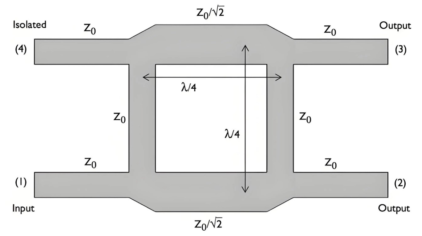
The branch-line coupler is designed symmetrically, which means that no matter which port is used as the input, it can still output power at the same frequency (evenly split). In the geometry shown in the diagram above, the port at the lower left corner is chosen as the input. We can swap the input and isolated ports, or we can flip the geometry horizontally so that the two output ports are on the left and the input and isolated ports are on the right.
2.Directional Coupler
A directional coupler is made up of two or more unshielded transmission lines. When the spacing between the conductors is smaller than the range of the electromagnetic field, the adjacent lines couple energy through mutual inductance (Lm) and mutual capacitance (Cm). This design allows a portion of the power from the main line to be coupled to the secondary line while making sure the signal only comes out from the specified port.
Features: the coupling level is controlled by the spacing between lines (like 10dB/20dB), it has high directivity, and moderate bandwidth (about one octave).
Applications: used for 5G base station power monitoring and spectrum analyzer signal sampling.
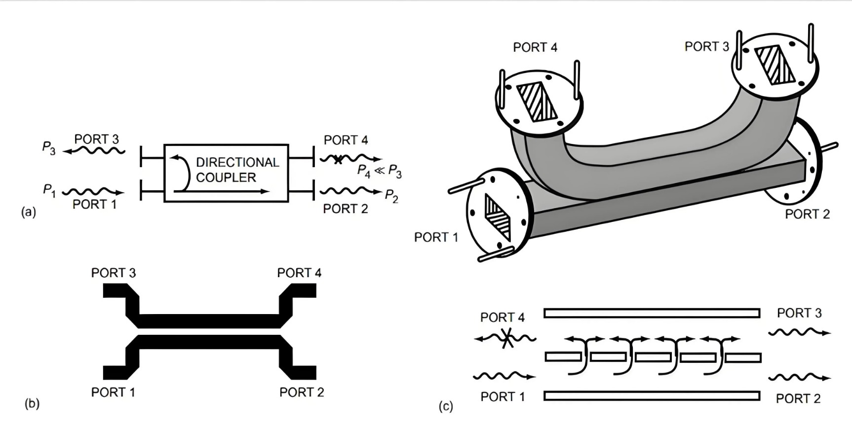
Coaxial directional coupler: Uses a coaxial transmission line structure, suitable for high-frequency bands (like millimeter wave applications), commonly used for power monitoring, signal isolation, and reflection measurement. Waveguide directional coupler: Consists of a main waveguide and a coupling waveguide, with signals separated through coupling windows on the isolating plate, mainly used for signal distribution and isolation in communication and radar systems.
3.Lange Coupler
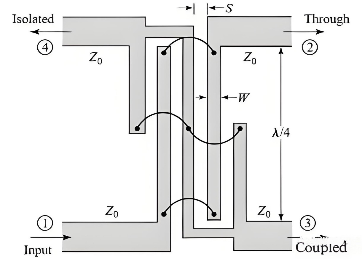
The Lange coupler is an orthogonal hybrid coupler with a 90° phase difference between the output ports (port 2 and port 3). The microstrip circuit design of the Lange coupler is shown in the figure below. To achieve strong coupling, four connected coupling lines are used here. These coupling lines easily achieve strong coupling and offer more than an octave of bandwidth. The tricky part is that it’s relatively hard to manufacture in practice, mainly because the lines are narrow and the gaps are very small. Also, the connecting lines that cross between the main lines are difficult to implement.
Features: wide bandwidth (up to 4:1), high isolation, high precision required for manufacturing, commonly used in millimeter-wave chips.
Applications: millimeter-wave communication modules, satellite payloads.
4.Rat-Race Coupler
A ring coupler is usually made up of a closed ring connected to four transmission lines, with the ring’s circumference designed to be 3/2 times the operating wavelength. Energy is transferred between the ports through electromagnetic coupling.
Features: output phase difference of 0° or 180°, supports high power (kW level); relatively wide bandwidth (about 40% relative bandwidth).
Applications: radar system signal combining, phased array antennas.
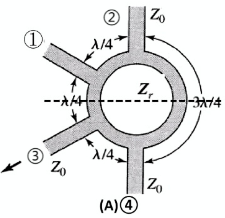
Classification by Function/Structure:
- Bidirectional Coupler: Can couple signals in both directions at the same time, meaning signals can travel both ways, and coupling detection can be done from either side.
- Directional Coupler: Only allows signals to couple in one direction, with a clear input and output.
- Branch Coupler (Power Divider): Distributes signals proportionally to multiple ports (like in a base station antenna array).
- Hybrid Coupler: Used for signal combination and phase control (such as 90°/180° hybrids).
- LTCC Coupler: Fits the miniaturization needs of devices and integrates with chip-level packaging technology.
- Waveguide Coupler: Meets the challenges of millimeter-wave and terahertz frequency communications.
S-Parameter Testing: The ‘Gold Standard’ for Measuring Performance
S-parameters (scattering parameters) are the key indicators for describing device performance in the RF field. By testing the S-parameters of various packaged couplers with a network analyzer and fixture, you can get a complete picture of their ‘signal monitoring capabilities’.
1. Pre-test Preparation
1. Fixture Design and Calibration
- Fixture requirements: use SMA/2.92mm connectors to ensure 50Ω impedance matching; control the elastic contact pressure of the fixture (±0.5N) to avoid damaging device pins
- Calibration steps: use TRL/thru calibration standards to eliminate fixture errors
2. DUT Installation Standards
Place the power divider in the center area of the test fixture, align it with the main body of the fixture, and complete a non-destructive press fit test.
2. Core Parameter Testing Process
| Parameter | Measurement Path | Test Procedure | Typical Acceptance Criteria |
|---|---|---|---|
| S11 | Port 1 Reflection | Read the minimum value across the full frequency band | < -20 dB |
| S21 | Port 1 → Port 2 | Record the maximum insertion loss | -0.5 ± 0.2 dB |
| S31 | Port 1 → Port 3 | Calculate the coupling factor | -20 ± 0.5 dB |
| S41 | Port 1 → Port 4 | Scan the full frequency band and find the maximum value | < -35 dB |
Key Calculations:
Directionality = |S41| – |S31| (unit: dB)
Isolation = |S41| (read directly)
3. Key Points to Note
If the isolated port isn’t connected to a 50Ω load → all S-parameters become invalid!
Load quality requirement: VSWR < 1.05 @ operating frequency Multi-channel synchronous measurements must activate S11/S21/S31/S41 at the same time → to ensure phase consistency
Environmental control: If temperature changes > 2℃, recalibration is needed RF cables should avoid bending with radius < 5cm
Conclusion
RF couplers play an important role in modern RF and microwave systems. They support key functions such as signal sampling, power distribution, signal combining, isolation, and phase control. Different coupler structures offer different advantages. For example, branch-line couplers provide 90° phase shifts, coupled-line directional couplers offer directional sampling, while Lange and rat-race couplers are suitable for wider bandwidth or specific phase-control requirements.
Selecting the right coupler requires more than looking at its frequency range. Coupling, directivity, isolation, insertion loss, bandwidth, and power handling should all be considered based on the system requirements. S-parameter testing also provides an effective way to evaluate coupler performance and verify whether key parameters meet the required specifications.
Looking for a reliable RF coupler for your application? Contact ZR Hi-Tech to discuss your requirements. Our team can help you find a suitable RF coupler solution based on your frequency range, coupling level, power handling, and other performance requirements.



