
Newsroom
Beginner’s Guide to HFSS Passive Device Design: Coupler and Power Divider Analysis
Microwave planar components are an essential part of microwave circuits. They mainly include microstrip transmission lines, couplers, filters, power dividers, and other passive devices. These components play a critical role in communication systems, radar, electronic warfare, and many other microwave applications. They typically operate over a frequency range of 300 MHz to 300 GHz. By using planar transmission structures such as microstrip lines, they enable key functions including microwave signal transmission, power distribution, and frequency filtering.
What Are Coupler And Power Divider
Directional couplers and power dividers are really important passive devices in the microwave and RF fields. They’re mainly used for signal distribution, combining, and coupling, and you’ll find them widely used in communication systems, radar systems, and broadcast TV transmission systems, among others.
1. Principles and Applications of Couplers
Couplers transfer a portion of the input signal based on the principle of electromagnetic coupling. Take a microstrip coupler as an example. When a high-frequency signal travels through the main transmission line, it generates an alternating electromagnetic field around the conductor. If a secondary transmission line is placed close to the main line, this field induces a voltage and current in the secondary line through electromagnetic induction. As a result, part of the signal is coupled from the main line to the secondary line. The coupling level depends on several factors, including the spacing between the two lines, the coupling length, and the characteristic impedance of the transmission lines. Different types of couplers use different coupling mechanisms and structural designs to achieve the desired performance.
(1) Directional Coupler
A directional coupler is a special type of RF coupler that transfers a fixed portion of the input signal from the main transmission line to a secondary transmission line. Under ideal conditions, the coupled signal propagates in only one direction.
Take a microstrip directional coupler as an example. By carefully designing the geometry of the transmission lines and the coupling length, the desired coupling ratio can be achieved. When an RF signal enters Port 1, a specified portion of the signal is coupled to Port 3 (the coupled port). At the same time, the signal at Port 2 (the isolated port) is theoretically zero.
This directional behavior is achieved through the phase relationships and electromagnetic coupling characteristics of the transmission lines. The coupled signals arriving at the isolated port are equal in amplitude but opposite in phase, causing them to cancel each other out. As a result, power is transferred only in the desired direction.
(2) Co-Directional and Contra-Directional Couplers
Co-directional and contra-directional couplers differ in the direction of the coupled signal. In a co-directional coupler, the coupled signal propagates in the same direction as the input signal along the auxiliary transmission line. In contrast, a contra-directional coupler transfers the coupled signal in the opposite direction.
Both types operate based on the principle of electromagnetic coupling. However, their transmission-line layouts and coupling structures are designed differently to achieve the required signal propagation direction. As a result, each type is suitable for different RF and microwave applications.
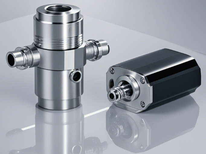
Directional Couplers in Base Station Power Monitoring
In communication base stations, couplers are widely used to monitor the output power of RF transmitters. They couple a small portion of the transmitted signal to a monitoring port without significantly affecting the main signal path. This allows engineers to measure the transmitter’s output power in real time and verify that it remains within the specified operating range.
For example, a GSM base station may use a 30 dB directional coupler to sample approximately 1/1000 of the transmitted power. The sampled signal is sent to monitoring equipment for accurate power measurement. If the output power deviates from the target value, the transmitter can be adjusted promptly to maintain stable communication performance.
The Principle and Application of Power Dividers
The basic function of a power divider is to split the input signal into two or more output signals according to a specified power ratio. Different power dividers achieve this using different circuit structures and design principles.
Take the Wilkinson power divider as an example. It is a passive RF component based on transmission line theory. When an RF signal enters the input port, the power is distributed to multiple output ports through carefully designed transmission lines. The characteristic impedance and electrical length of these transmission lines are optimized to provide the desired power split while maintaining good impedance matching and high isolation between the output ports.
In a two-way Wilkinson power divider, the input power is ideally divided equally between Port 2 and Port 3, with each output receiving half of the input power. Under ideal conditions, the two output ports remain well isolated, minimizing signal interference and improving system performance.
Different types of power dividers use different operating principles and structures to achieve specific power distribution requirements.
- Wilkinson power divider: As mentioned before, it improves isolation between ports by adding isolation resistors between the output ports. When a signal enters the input port, the design of the transmission line structure and characteristic impedance ensures that the power is evenly distributed between the two output ports, and the isolation resistors prevent signals from interfering with each other between the output ports.
- Branch-Line Power Divider: A branch-line power divider is another widely used type of RF power divider. It distributes power through a network of branch transmission lines. By optimizing the length and characteristic impedance of these lines, the input signal can be divided into multiple output signals. Compared with a Wilkinson power divider, it has a simpler structure. However, it typically provides lower isolation between the output ports.
Power Dividers for Radar Antenna Arrays
In radar transmission systems, power dividers distribute high-power RF signals to multiple antennas. This allows multiple antenna elements to operate together as a radar antenna array.
For example, in a phased array radar, a power divider evenly splits the transmitter’s power among a large number of antenna elements. By controlling the phase and amplitude of each element, the radar can electronically steer and focus its beam without mechanical movement.
Power dividers are also used on the receiving side. They combine the weak echo signals collected by multiple antenna elements into a single receiving channel. This increases the received signal strength and improves the radar’s detection range, sensitivity, and target detection accuracy.
Simulation of Coupler and Power Divider Design Based on HFSS
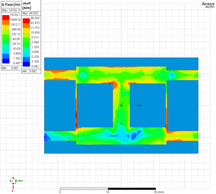
Common simulation tools used for couplers and power dividers include HFSS, CST, ADS, ZWSim-EM, and Rsoft. Among them, HFSS (High Frequency Structure Simulator) is an electromagnetic simulation software based on the finite element method, capable of accurately modeling and analyzing the electromagnetic performance of microwave devices like antennas, couplers, and power dividers. Users can create 3D models, set material properties, boundary conditions, and excitation sources, and simulate device performance, such as coupler coupling, directivity, VSWR, and power divider insertion loss, isolation, and return loss. For example, when designing a microstrip directional coupler, HFSS can be used to accurately predict its performance at different frequencies.
Conclusion
Couplers and power dividers are essential RF passive components that enable efficient signal distribution, monitoring, and power management in microwave systems. From wireless communications and radar to satellite and test applications, selecting the right component and validating its performance with HFSS can significantly improve system reliability and design efficiency.
Looking for high-performance RF couplers or power dividers? Contact ZR Hi-Tech to explore our wide range of RF and microwave passive components. Our engineering team is ready to help you find the right solution for your application.



