
Newsroom
RF Amplifier Performance Testing: A Complete Guide to Methods, Parameters, and Equipment
In wireless communication systems, the RF power amplifier (PA) is one of the most important components in the RF front end. Its primary function is to amplify low-power RF signals to the required output power level.
Wireless signals experience significant attenuation during transmission. To maintain stable communication quality, the modulated signal must be amplified before it is transmitted through the antenna.
For this reason, the RF power amplifier is often regarded as the heart of a wireless communication system. Its performance has a direct impact on overall system quality. Almost every wireless communication system relies on an RF power amplifier. Because of its critical role, the RF power amplifier is often called the “crown jewel” of RF front-end components.
To ensure reliable operation, engineers must accurately evaluate amplifier performance. This article introduces the most important RF power amplifier performance parameters. It also explains the common testing methods used to measure and verify them.
Preparing for Power Amplifier Testing
Before preparing for the test, we need to get the equipment and components needed for testing ready, such as the following list: power meter, signal source, spectrum analyzer, filter, coupler, attenuator, DC power supply, digital waveform generator, test or evaluation board, several chips, and other components or devices.
Once we have all of these ready, we can refer to the diagram below to set up the test environment.
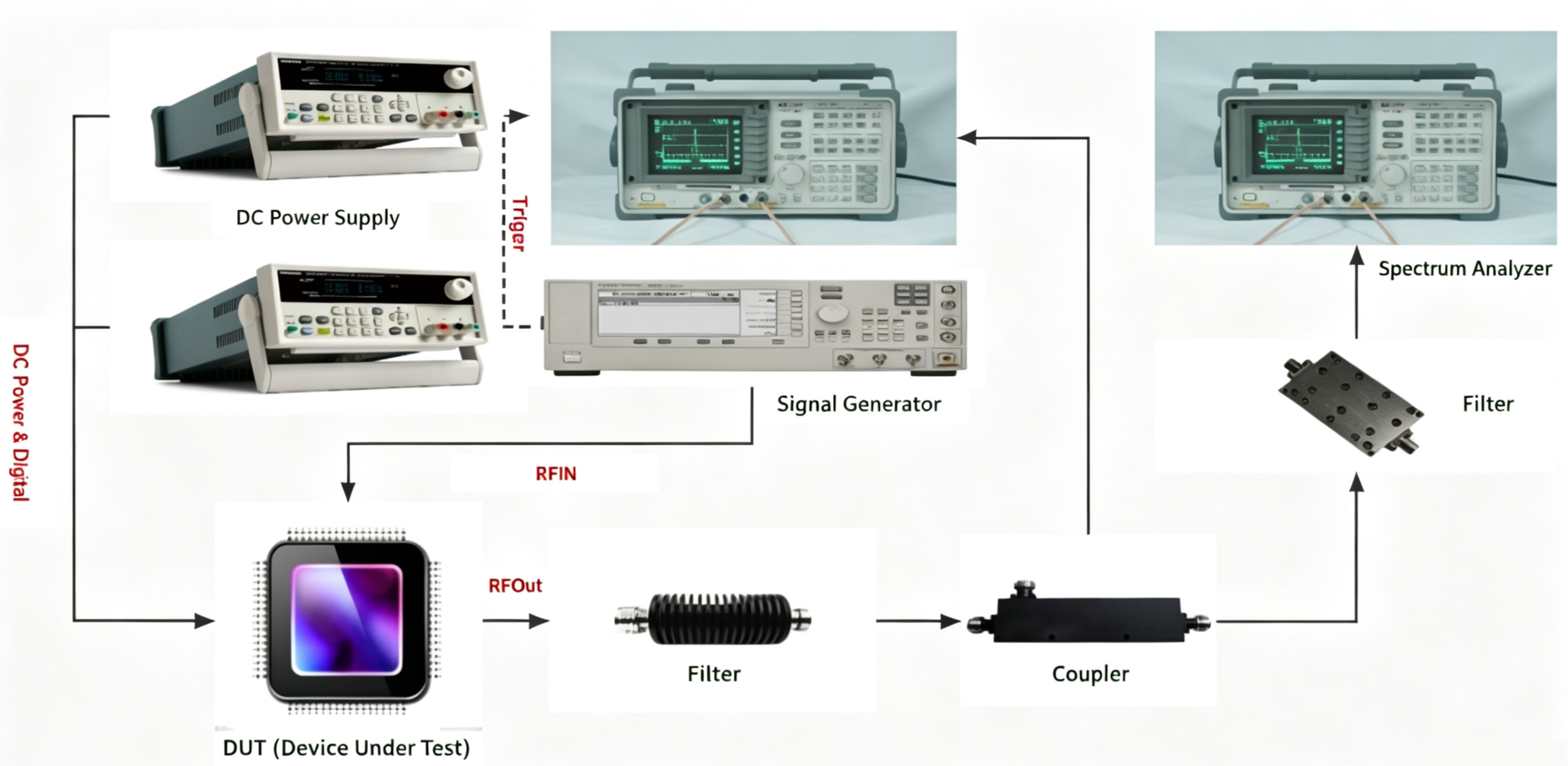
Before testing, it’s important to keep a few things in mind:
- check if the circuit is working properly before powering it on to avoid short circuits or impedance mismatch issues;
- make sure to connect the correct attenuator during testing to prevent damage to the equipment and test chips;
- verify that the RF connections are all good before transmitting any RF signals;
- set the instrument compensation values correctly;
- for accurate testing, calibrate the equipment you’re using against the same reference device.
Next, we’ll go over the testing principles and methods for a few common metrics together.
Test of Maximum Output Power
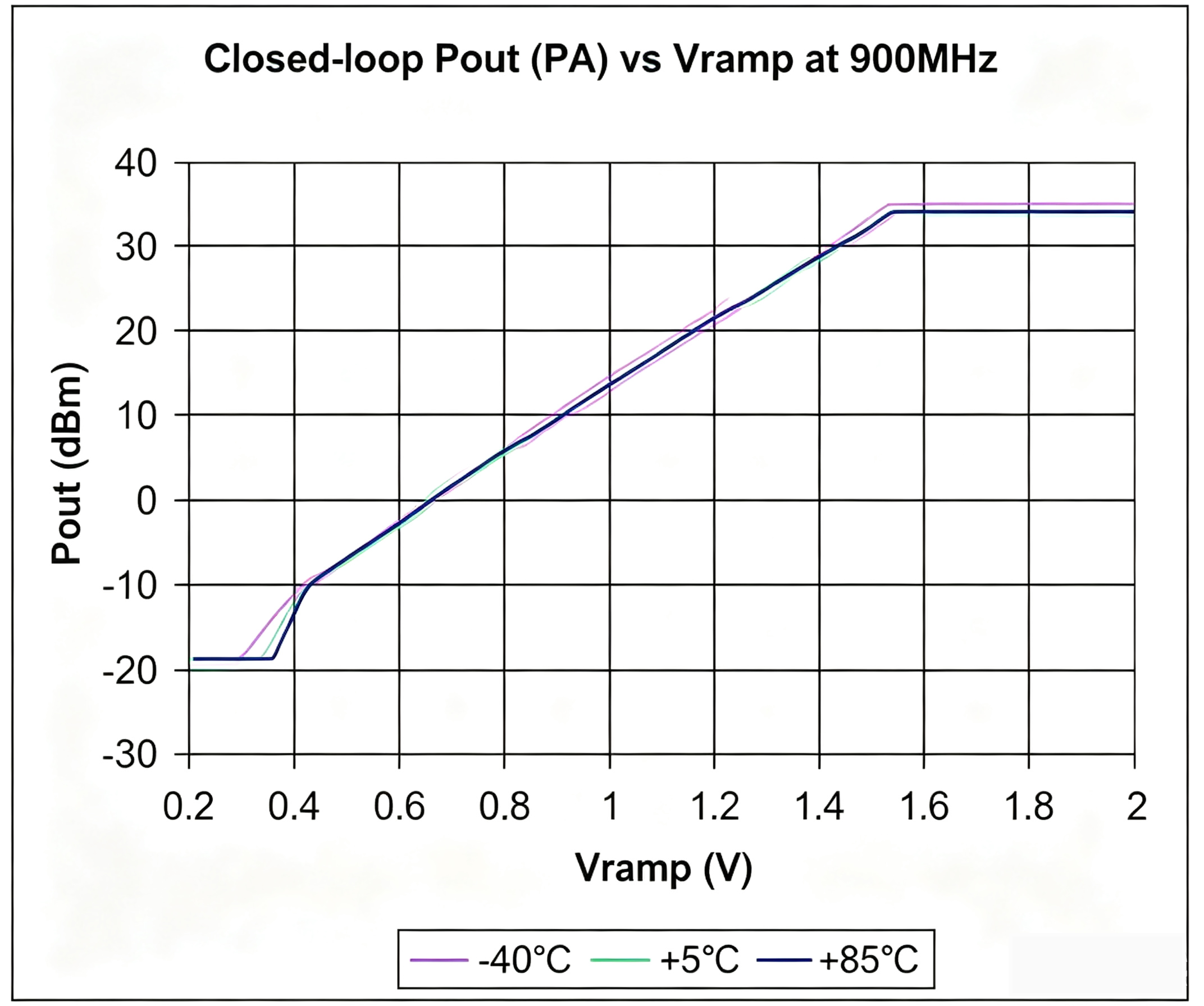
In GSM mode, the RF power amplifier usually operates in the nonlinear region. When the output power (Pout) reaches its maximum value, increasing the input power (Pin) no longer increases the output power. Instead, the output power is mainly controlled by the VRAMP voltage.
During mass production, manufacturers typically measure the maximum output power (Pout Max) of the PA. The test is performed by applying the specified supply voltages to all pins. A standard RF input signal is then applied. Next, the VRAMP voltage is increased to its maximum value. Finally, the output signal level is measured.
When testing output power in GSM mode, a 12.5% duty cycle is typically required. There are two common methods for generating this duty cycle.
The first method is to control the duty cycle of the Tx Enable signal. The second method is to control the RF input signal waveform. This approach is commonly known as burst signal generation.
Testing the Power Added Efficiency (PAE) of a Power Amplifier
Added power efficiency (PAE) refers to the ratio of the difference between the output signal power and the input signal power to the DC power consumption. This metric lets you see how much loss an amplifier has during the power conversion process.
One thing to pay special attention to here is that the output power and input power need to be converted from dBm to mW or W before doing any calculations.
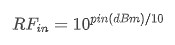
You can calculate the PAE by plugging the measured voltage, current, input, and output power into the formula above.
Measuring Pin and Pout of a Power Amplifier
This testing method is typically used for an RF power amplifier operating in the linear region. In this region, the output power (Pout) increases as the input power (Pin) increases. In theory, the desired output power can be obtained by adjusting Pin. Therefore, the required Pin becomes the value to be measured. This process can also be automated using a simple algorithm.
Before the test begins, Pin is set to a relatively low value. This ensures that the initial output power (Pout₀) is slightly below the target Pout. Because Pin and Pout have an approximately linear relationship, Pin can first be increased by the difference between the target Pout and Pout0.The output power is then measured again. If it reaches the target value, the test is complete.
If the measured Pout is still different from the target, Pin is adjusted upward or downward according to the remaining error. This adjustment process is repeated several times. In most cases, the correct Pin can be found quickly with only a few iterations.
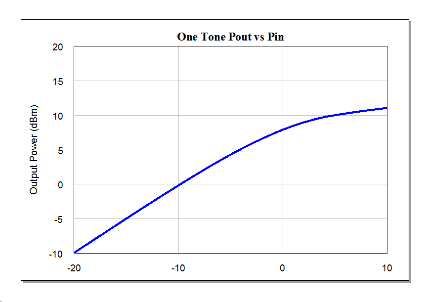
Everyone should note here, when adjusting the pin, it’s best to do it from small to large.
Measurement of Power Amplifier Harmonics
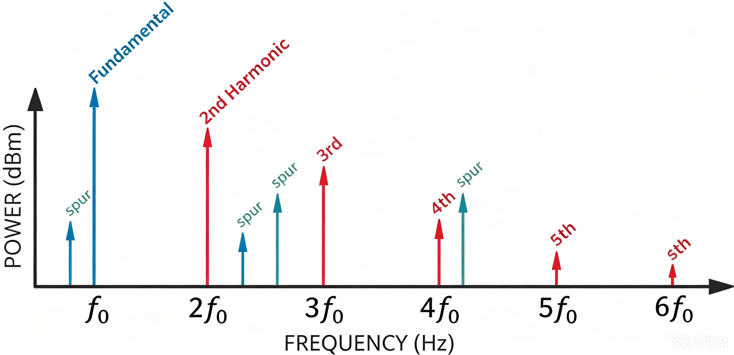
For harmonic testing, you usually only need to test the 2nd and 3rd harmonics. Harmonics higher than the 4th order carry higher frequencies. They also suffer much stronger signal attenuation. Their power levels are therefore relatively low. You do not need to test them in most cases. You will require one special component for this test: a filter. Power amplifiers deliver very high output power. Even after adding an attenuator, the test instrument may produce extra harmonics.
These unwanted signals will distort your PA harmonic measurement data. This is why a high-pass filter is necessary during harmonic testing. It blocks the main carrier signal before you capture harmonic signals. You can refer to the test setup diagram shown above for reference. After filtering the carrier, measure harmonics at their respective frequency points. This simple step ensures you get far more precise test results.
Measurement of RF Amplifier EVM
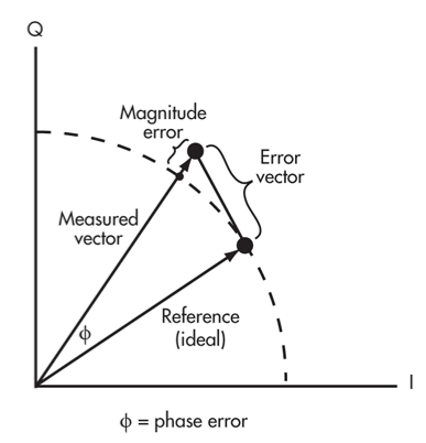
EVM stands for Error Vector Magnitude. It measures the amplitude and phase errors of a standard modulated signal and is an important indicator of signal quality. As shown in the picture below, it can be calculated by the vector difference between the signal and the ideal signal:
When testing the EVM, we also need to prepare the modulated signal. After applying the modulated signal to the chip under test, we use a spectrum analyzer to select the correct modulation type and parameters for testing.
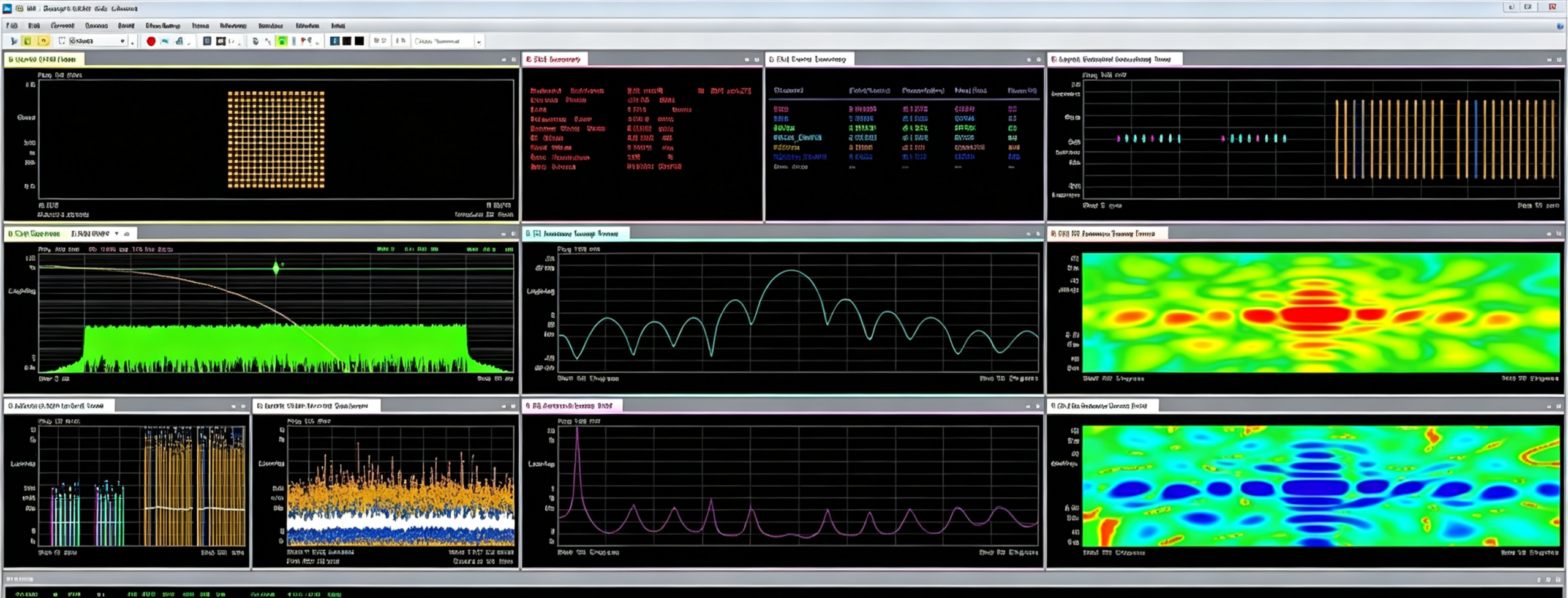
It’s worth noting that when testing EVM and ACLR, you need to pay attention to the appropriate carrier input power. If the input power is too high, it can cause worse linearity and higher EVM.
Conclusion
Accurate RF power amplifier testing is essential for ensuring stable performance, high efficiency, and reliable wireless communication systems. From maximum output power, power-added efficiency (PAE), and Pin/Pout characterization to harmonic performance and Error Vector Magnitude (EVM), each parameter provides valuable insight into how an amplifier will perform under real-world operating conditions.
By following proper test procedures, using the right equipment, and understanding the significance of each measurement, engineers can optimize RF power amplifier designs, improve production consistency, and ensure compliance with communication standards. As wireless technologies continue to evolve toward higher frequencies, wider bandwidths, and more demanding performance requirements, precise RF testing will remain a critical part of product development and quality assurance.
At ZR Hi-Tech, we specialize in the design and manufacturing of high-performance RF and microwave components, including RF Power Amplifiers, Low Noise Amplifiers (LNAs), PIN Diode Switches, Power Dividers, Directional Couplers, Hybrid Couplers, and Cavity Filters. Backed by strong R&D capabilities and advanced manufacturing facilities, we provide reliable RF solutions for wireless communications, satellite systems, aerospace, industrial applications, and test equipment.
Contact ZR Hi-Tech today to discuss your RF power amplifier requirements or explore our complete portfolio of RF and microwave products. Our team is committed to helping you achieve outstanding performance in your next wireless communication project.



