
Newsroom
A Detailed Look at Parallel Coupled Line Directional Couplers: Theory, Odd-Even Mode Design & R...
We have covered directional couplers before. We walked through their basic theories, key performance specs, and the design workflow of branch-line directional couplers, the most widely used type. Today, we move on to another mainstream variant: parallel-coupled line directional couplers. If you haven’t read our earlier articles yet, feel free to review them to follow along easily.
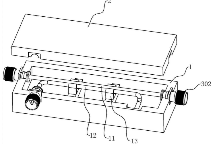
Introduction to Parallel Coupled Line Directional Couplers
Analysis of Parallel Coupled Line Directional Coupler
Qualitative Analysis
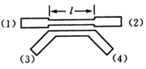
The picture above shows a common parallel-line directional coupler, with a coupling line length L. Let’s assume port 1 is where the RF signal enters, and obviously, port 2 is the through port for the signal. Now let’s qualitatively analyze the RF signal characteristics at ports 3 and 4 to figure out which is the coupled port and which is the isolated port?
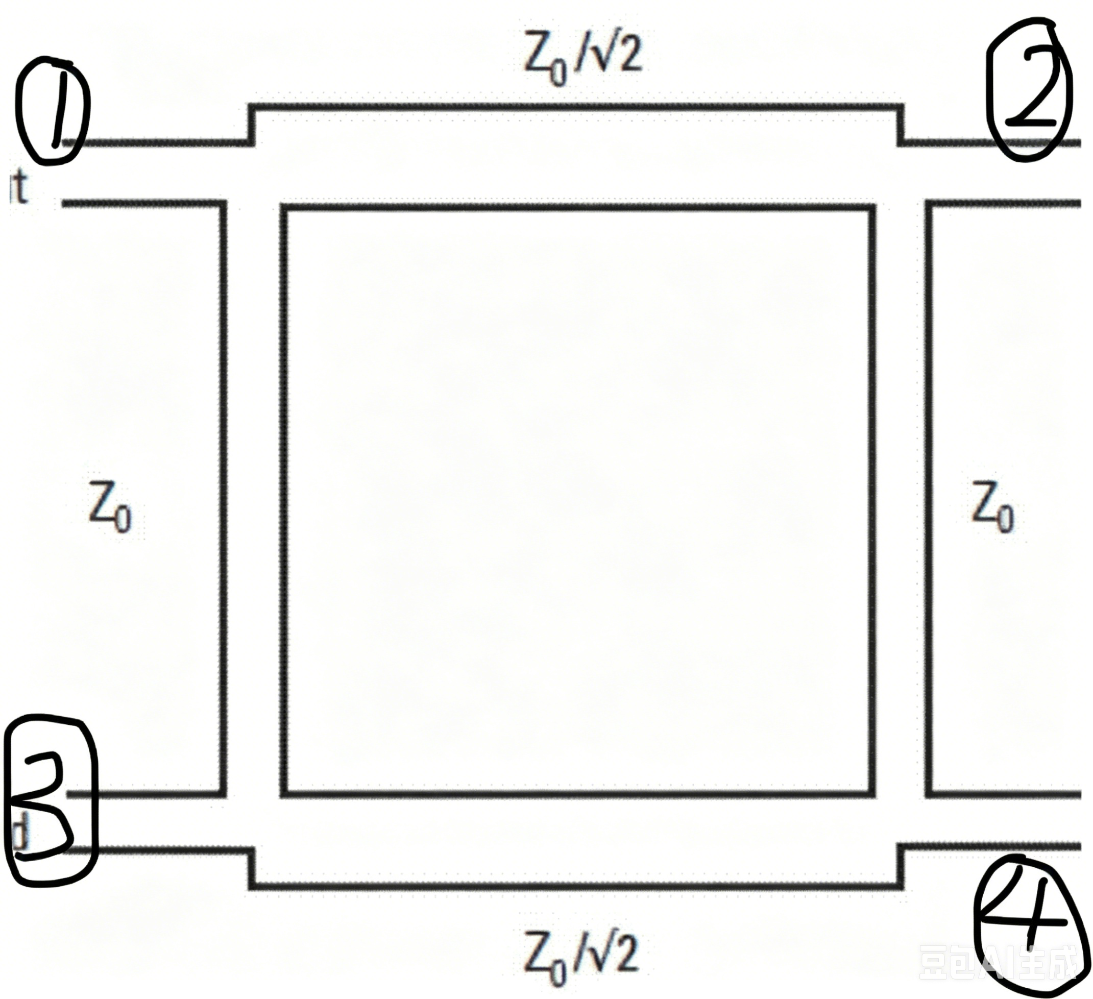
Let’s first recall the qualitative analysis of the branch-line directional coupler. We use the phase difference of the signals to determine the coupled port and the isolated port. Now look at the figure – do you know which one is the isolated port and which one is the coupled port? For RF engineers, it’s recommended to remember this well.
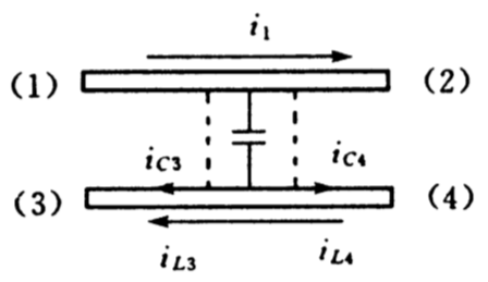
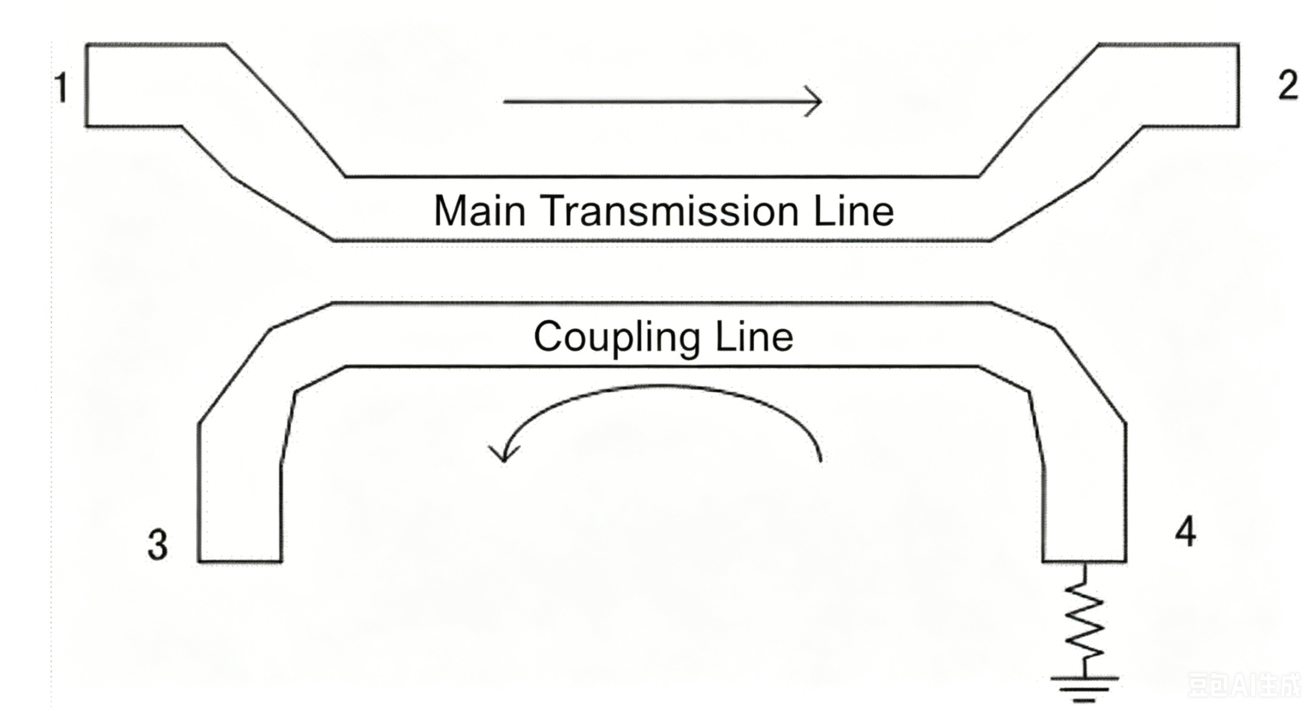
- Two tightly spaced transmission lines form a coupling capacitance C between them. The smaller the gap between lines, the higher this capacitance. Capacitively coupled currents ic3 and ic4 flow toward both ends of the coupled line.
- An RF signal i1 travels along the main line. Per electromagnetic induction rules, an induced current iL will be generated on the coupled line. The flow direction of iL opposes that of i1.
At Port 3, ic3 and induced current iL3 flow in the same direction, so they add constructively.
At Port 4, capacitive current ic4 and induced current iL4 flow opposite to each other, leading to signal cancellation.
Quantitative Analysis
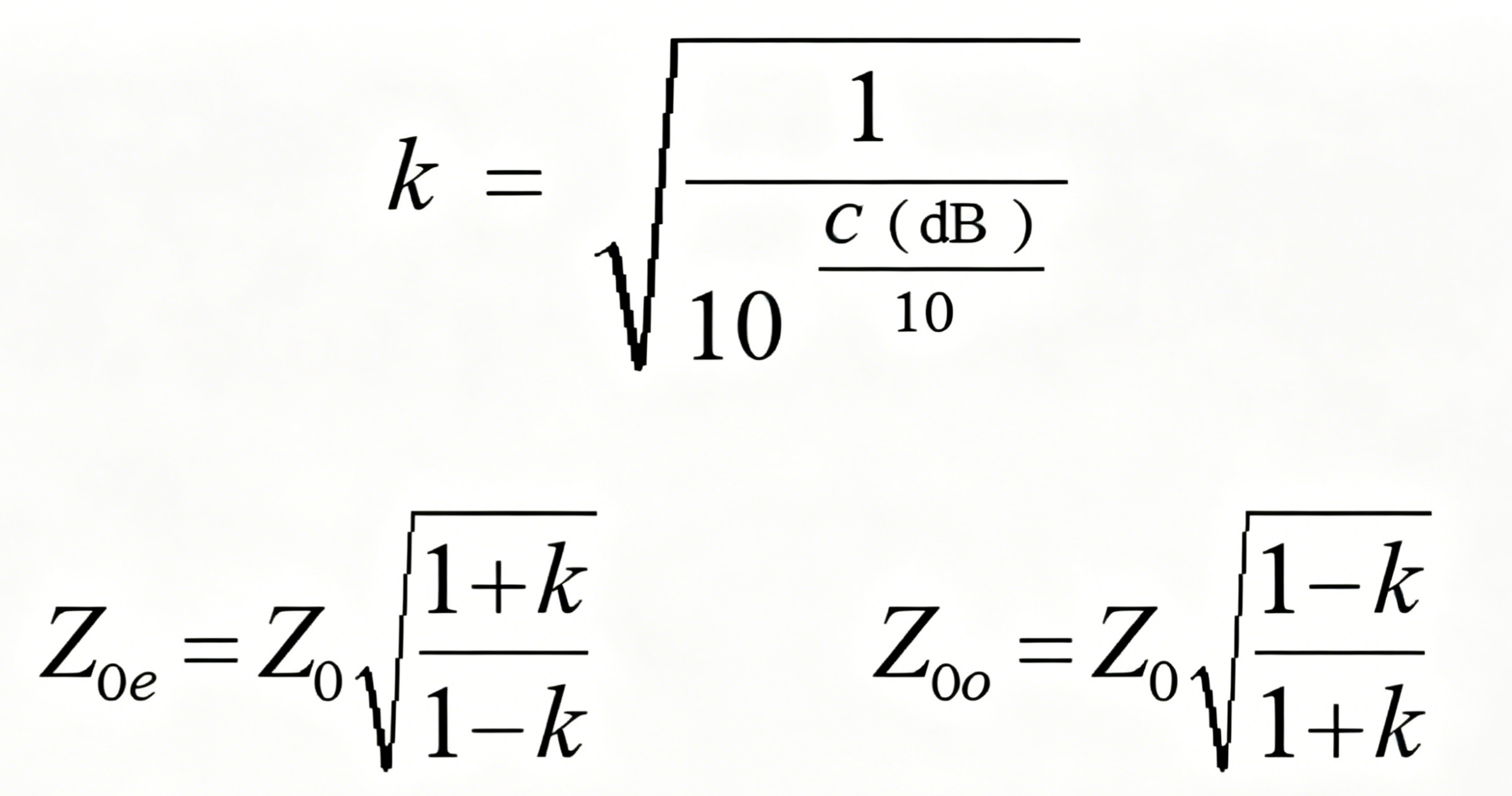
Parallel Coupled Line Directional Couplers Design Example
Design a parallel-coupled line directional coupler with the specifications: center frequency 3.5 GHz, coupling factor C = 15 dB, output line characteristic impedance 50 Ω, dielectric substrate εr = 9.6, h = 1 mm.
Step 1: Plug into the formula and calculate:
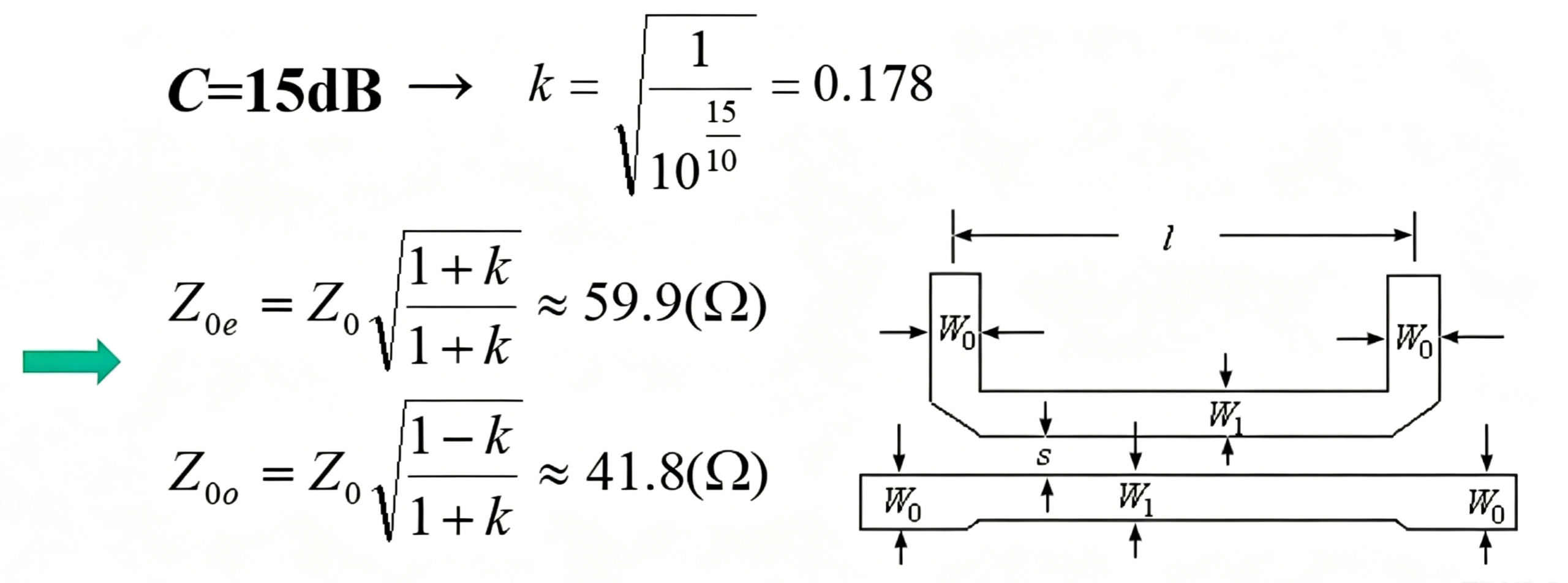
W1/h = 0.97, W1 = 0.97mm; s/h = 0.62, s = 0.62mm. The length of the coupled line segment is roughly considered equal to a quarter wavelength of a single uncoupled line. Using the microstrip line formula, the microstrip line width is calculated as: W0 = 0.99mm
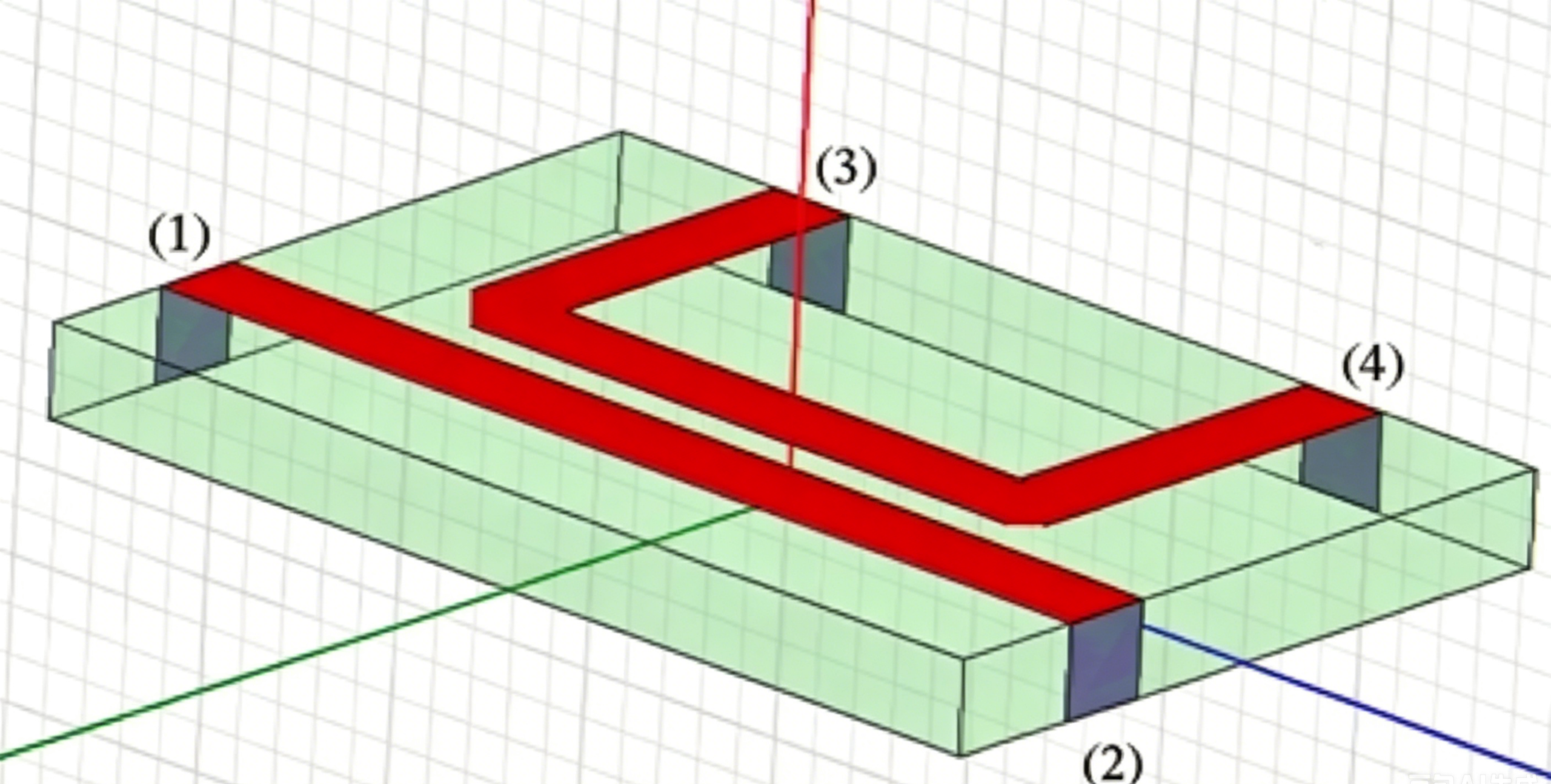
Step 2: Import into HFSS for modeling and simulation:
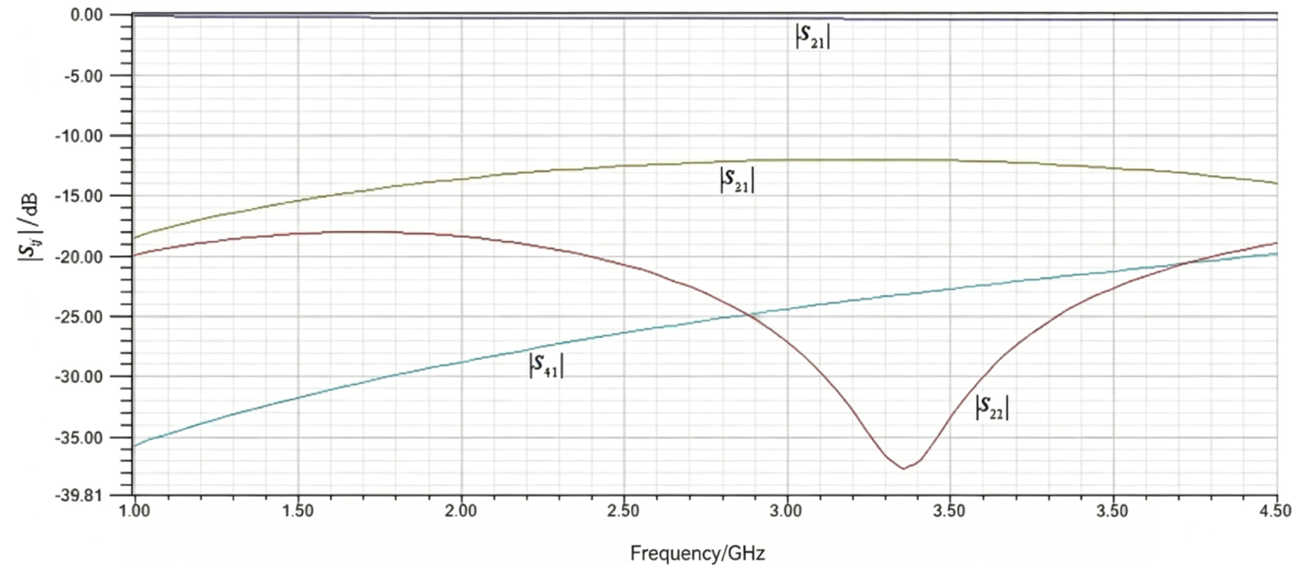
Step 3: The simulation results are as follows:
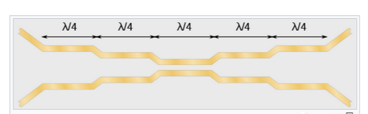
Wideband Design of A Parallel-line Directional Coupler
There are many types of couplers, but the common ones are these two: branch line and coupled line. There’s also a microstrip directional coupler called the Lange coupler that achieves tight coupling. We’ll learn about it in a later post.
Conclusion
Parallel coupled line directional couplers are a key RF passive component widely used in communication systems, radar, aerospace, and measurement applications. In this article, we explored their operating principles, odd-even mode analysis, design process, and HFSS simulation results.
Compared with branch-line directional couplers, parallel coupled-line couplers feature a different port configuration and provide a flexible solution for RF signal coupling. By optimizing coupled-line dimensions and using multi-section structures, engineers can achieve better bandwidth performance and meet the requirements of modern wideband RF systems.
As RF technologies continue to develop toward higher frequencies and broader bandwidths, parallel coupled-line directional couplers will remain an essential component in advanced microwave designs. ZR Hi-Tech provides high-performance RF solutions, including directional couplers, power dividers, and other microwave components, supporting various demanding RF applications.



