Newsroom
A Detailed Look at Branch-Line Directional Coupler: Principles, Simplified Formulas and Simulation
2026-06-17
1. Introduction
In our previous article About Directional Coupler | Types, Applications and more…, we elaborated on basic information of directional couplers, including definitions, core performance indicators, typical applications and common classifications. Numerous RF engineers have raised follow-up questions: how does signal cancellation work inside microstrip branch-line directional couplers? Is it necessary to deduce complicated odd-even mode formulas manually? How to complete impedance calculation and PCB layout simulation efficiently for practical projects?
Based on the textbook by Professor Luan Xiuzhen, this article avoids cumbersome mathematical derivation. It explains the operating mechanism of branch-line directional couplers through intuitive wave superposition logic, summarizes practical design formulas, and presents a complete design case of a 5GHz 3dB microstrip branch-line directional coupler. We also compare bandwidth performance between single-section and multi-section branch-line structures to supplement the full knowledge system of directional couplers.
2. Basic Structure of Branch-Line Directional Coupler
As one of the most widely used four-port directional couplers in RF circuits, branch-line directional couplers belong to quadrature couplers that output signals with a fixed 90° phase difference. They are extensively adopted in power combining, balanced amplifiers, I/Q mixers and antenna feeding networks.
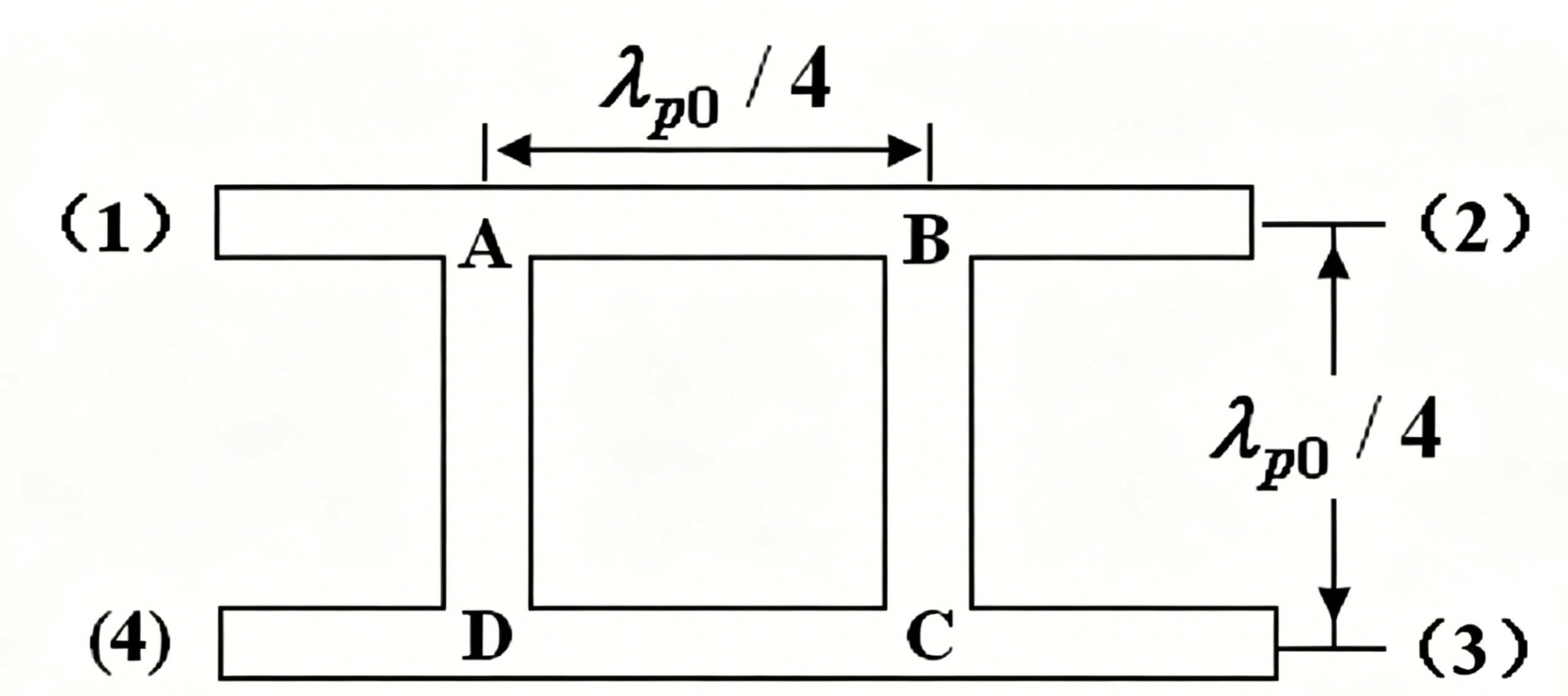
A standard single-section branch-line directional coupler consists of four quarter-wavelength transmission lines, namely the main line, auxiliary line and two parallel branch coupling lines. The four ports follow a fixed layout: Port 1 (input), Port 2 (through), Port 3 (coupled), Port 4 (isolated). In terms of transmission medium, it can be fabricated with coaxial lines, striplines or microstrips. Microstrip branch-line directional couplers account for over 95% of applications in civil RF and 5G microwave systems due to compact size, PCB integration and low manufacturing cost.
Core structural specification: The electrical length of all main lines, auxiliary lines and branch coupling lines equals one quarter wavelength at the center frequency, and all ports match the standard 50Ω system impedance by default.
3. Qualitative Analysis of Coupling and Isolation Mechanisms
All directional couplers achieve directional characteristics via the same core principle: multi-path electromagnetic waves cancel each other at the isolated port and superimpose constructively at the coupled port. Engineers can master the mechanism merely through path difference analysis without advanced electromagnetic field theory. We analyze signal transmission paths with Port 1 as the input terminal:
3.1 Port 4 (Isolated Port): Complete Signal Cancellation
Two independent transmission paths lead signals from Port 1 to Port 4:
-
Path 1: Port 1 → transverse branch line → Port 4 (1/4 wavelength path)
-
Path 2: Port 1 → main line → Port 2 → auxiliary line → Port 4 (3/4 wavelength path)
The path difference between the two routes is 1/2 wavelength, corresponding to a 180° phase difference. The two signal components have similar amplitudes and opposite phases, resulting in vector cancellation at Port 4 with theoretically infinite isolation. This is the fundamental reason for the unidirectional transmission of directional couplers.
3.2 Port 2 (Through Port): Main Signal Reservation
Signals also travel via two paths to Port 2 with a theoretical 180° phase difference. However, the signal amplitude transmitted directly through the main line is far larger than the leakage signal passing through branch lines. Only a tiny portion of signals cancel out, and most residual signals output from Port 2. The attenuated power here is defined as the coupling loss of directional couplers.
3.3 Port 3 (Coupled Port): Constructive Signal Superposition
Both signal paths reach Port 3 with an identical path length of 1/2 wavelength, leading to in-phase superposition. Meanwhile, signals at the through port and coupled port feature a fixed 90° phase offset, hence the official name 90° branch-line directional coupler.
4. Odd-Even Mode Analysis: Skip Derivation and Memorize Practical Formulas
Academic odd-even mode analysis involves four-port network matrix transformation and impedance equivalence, which is overly complicated and rarely used in actual RF engineering. We eliminate redundant mathematical deduction and summarize two universal formulas applicable to all branch-line directional coupler designs.
4.1 Brief Introduction to Odd-Even Mode Principle
The symmetric four-port coupling network can be decomposed into two independent two-port networks under two excitation states. Under even-mode excitation, no current flows on the symmetric plane, which is equivalent to an open circuit. Under odd-mode excitation, no voltage exists on the symmetric plane, which is equivalent to a short circuit. Final port impedance parameters are calculated by superposing results of the two states.
4.2 Two Core Practical Formulas
Define coupling degree as C (dB) and system characteristic impedance as Z₀=50Ω:
1. Impedance of branch coupling line: $$Z_b = \frac{Z_0}{\sqrt{1-10^{-C/10}}}$$
2. Impedance of main and auxiliary lines: $$Z_a = Z_0 \times \sqrt{\frac{10^{-C/10}}{1-10^{-C/10}}}$$
Note: These two formulas apply to 90% of branch-line directional couplers with 3dB, 6dB and 10dB coupling degrees without parameter modification.
5. Practical Design Case: 5GHz 3dB Microstrip Directional Coupler
5.1 Design Specifications
Center frequency: 5GHz; Port impedance: 50Ω; Coupling degree: 3dB; Substrate relative permittivity: εr=9.6; Substrate thickness: h=0.8mm
5.2 Fast Impedance Calculation via MATLAB Code
C=3; % 3dB coupling degree V3=sqrt(1/(10^(3/10))) b=1/(sqrt(1-V3^2)) a1=b*V3 Z0=50; Za=Z0/a1 Zb=Z0/b
Calculation results: Main/auxiliary line impedance Za=50Ω, branch coupling line impedance Zb=35.4Ω
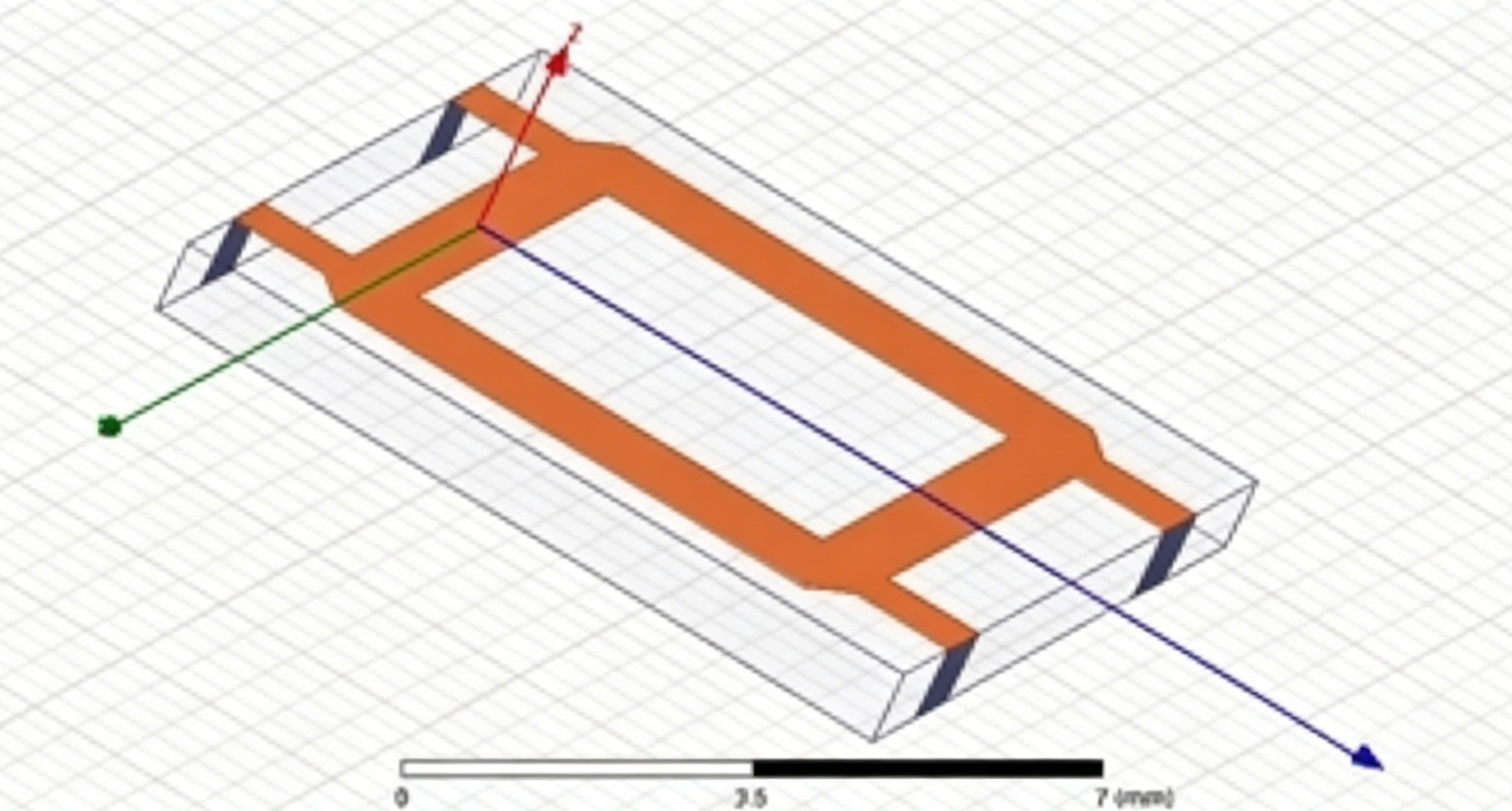
5.3 Microstrip Dimension Conversion
According to standard microstrip impedance calculation formulas matching the substrate parameters: the line width of 50Ω microstrip is 1.02mm, and the line width of 35.4Ω microstrip is 1.76mm. The electrical length of all quarter-wavelength lines is 9.2mm at 5GHz.
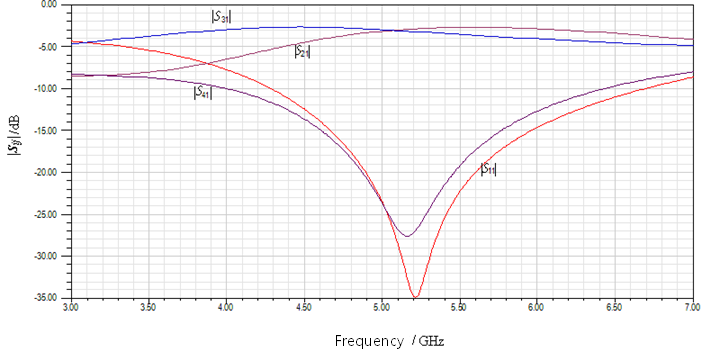
5.4 Simulation Performance Prediction (ADS/HFSS)
Key simulated indicators of the single-section coupler at 5GHz: Insertion loss ≤ 0.2dB, coupling degree = 3.02dB, port isolation ≥ 22dB, VSWR < 1.2, which meets general RF test standards.
6. Bandwidth Comparison: Single-section vs Multi-section Branch-Line Couplers
Single-section branch-line directional couplers suffer from narrow effective bandwidth, only ±5% of the center frequency. They are only suitable for fixed-frequency applications such as point-frequency radar systems.
Multi-section branch-line directional couplers adopt 3 to 5 sets of cascaded coupling branches to optimize wideband impedance matching, expanding effective bandwidth to ±20% of the center frequency. They are preferred for wideband RF testing and multi-band base station systems. The tradeoffs include larger PCB footprint and slight insertion loss increase of 0.1-0.3dB.
7. Conclusion
As fundamental four-port passive components, branch-line directional couplers rely on wave path difference to realize signal cancellation and superposition, delivering stable 90° quadrature signals. RF engineers do not need to master complex odd-even mode derivation; memorizing two impedance formulas is sufficient for conventional frequency design. Single-section structures fit narrowband fixed-frequency scenarios, while multi-section structures adapt to wideband RF systems.
When selecting directional couplers, prioritize bandwidth requirements before conducting microstrip layout conversion. For customized directional coupler selection, layout optimization and performance debugging support, please contact technical engineers at ZR Hi-tech.