Newsroom
What Are Spurious Interference, Intermodulation Interference, and Blocking Interference?
Spurious interference is mainly caused by insufficient receiver sensitivity. The output signal of a transmitter is usually a high-power signal. During the generation of a high-power signal, relatively high levels of spurious emissions are generated outside the transmitter’s operating frequency band. If the amplitude of these spurious emissions is high enough to fall within the receiving band of another system, the input signal-to-noise ratio (SNR) of the receiving system will decrease, resulting in degraded communication quality. Spurious interference is generated by the transmitter and includes thermal noise generated and amplified by the power amplifier, system intermodulation products, and other interference received within the receiver frequency range.
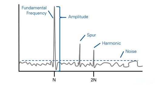
Spurious interference occurs when spurious radiation outside the operating frequency band of one system falls within the receiving band of another system. Spurious interference directly affects the receiver sensitivity of the system. To reduce the impact of spurious interference, either the interference must be filtered at the transmitter or the interfering source must be kept at a sufficient distance. If the spurious emission falls within the receiving band of a system at a relatively high amplitude, the affected receiver cannot filter out the spurious signal. Therefore, a filter must be added at the transmitter output to control spurious interference. Through interference analysis, the required isolation level can be calculated to reduce the impact of interference on the system to an appropriate level, i.e., to keep the interference level from causing a significant degradation in sensitivity. In a POI (Point of Interface) combining solution, the maximum isolation requirement among multiple systems is selected as the engineering requirement. Spurious interference is generated by the transmitter and includes thermal noise generated and amplified by the power amplifier, system intermodulation products, and other interference received within the receiver frequency range.
Third-order intermodulation interference: Third-order intermodulation refers to a spurious signal generated when, due to nonlinear factors in a system, the second harmonic of one signal mixes with the fundamental frequency of another signal. For example, the second harmonic of F1 is 2F1, which combines with F2 to generate the spurious signal 2F1-F2. Because one signal is a second harmonic (a second-order signal) and the other is a fundamental signal (a first-order signal), their combination produces a third-order signal. Among these products, 2F1-F2 is called a third-order intermodulation signal, and it is generated during the modulation process. Since the beat signal is generated by the mutual modulation of these two signals, the newly generated signal is called a third-order intermodulation distortion signal. The process that generates this signal is called third-order intermodulation distortion. Because the F2 and F1 signals are relatively close in frequency, 2F1-F2 and 2F2-F1 can also interfere with the original baseband signals F1 and F2. This is third-order intermodulation interference.
Quantitative Analysis. To improve channel utilization, mobile communication systems generally use multi-channel shared networking, in which M mobile stations share N channels (M >> N). A mobile station communicates through an idle channel selected by the base station. When a mobile communication system operates with N evenly spaced channels, intermodulation interference in the entire system can be broadly classified into: intermodulation interference generated by the mobile-station receiver; intermodulation interference generated by the base-station receiver; intermodulation interference caused by mutual coupling between base-station transmitters; intermodulation interference caused by mutual coupling between mobile-station transmitters; interference to mobile-station reception caused by intermodulation products generated at a mobile-station transmitter due to mutual coupling between mobile-station and base-station transmitters; and interference to base-station reception caused by intermodulation products generated at a base-station transmitter due to mutual coupling between base-station and mobile-station transmitters. A brief quantitative analysis of these six types of intermodulation interference is provided below.
(A) Intermodulation interference generated by the mobile-station receiver. When several base-station channels transmit simultaneously, the intermodulation interference generated by nonlinearities in the front-end circuit of the mobile-station receiving section is co-channel interference.
(B) Intermodulation interference generated by the base-station receiver. When two or more mobile stations transmit simultaneously in an area near the base station, intermodulation interference can likewise be generated in the base-station receiver. This type of interference is independent of EI and EC, and the D(N, P) term in Equation (2) can be disregarded. When EI = EIMAX and EC = ECMIN, for example, four mobile stations M1, M2, M3, and M4 are operating simultaneously, with M1, M2, and M3 near the base station and M4 at the edge of the service area (ECMIN ≈ ES, where ES is the receiver sensitivity specification).
(C) Intermodulation interference caused by mutual coupling between base-station transmitters. For mobile stations in the same system, this type of interference is co-channel interference. If all channels in the system are operating, as long as the intermodulation product is more than 15 dB below the signal, its impact on the signal-to-interference ratio at the mobile-station receiver output is not significant. However, if one channel is not operating—for example, in an N=4 system where fBT1, fBT2, and fBT3 are operating while fBT4 is not—the third-order intermodulation Type II product fBT2+fBT3-fBT1=fBT4=fMR4 may cause the mobile-station receiver to stop on the wrong channel and result in call loss. For an adjacent system, this type of interference is considered spurious radiation and must be more than 60 dB below the carrier power (or less than 25 µW).
(D) Intermodulation interference caused by mutual coupling between mobile-station transmitters. Assume that two mobile stations near the base station and one mobile station at the edge of the system service area are operating simultaneously (as shown in Figure 2). The intermodulation products generated by mutual coupling between the two mobile-station transmitters near the base station may affect the base station’s normal reception of the signal from the mobile station at the edge of the service area. This type of interference is an instantaneous random interference. When there are relatively few mobile stations, its impact is not significant.
(E) Interference to mobile-station reception caused by intermodulation products generated at a mobile-station transmitter due to mutual coupling between mobile-station and base-station transmitters.
(F) Interference to base-station reception caused by intermodulation products generated at a base-station transmitter due to mutual coupling between base-station and mobile-station transmitters. In summary, the more serious types of interference are (A), (B), and (D), and quantitative analysis must be performed carefully during engineering design.
Blocking interference. When a relatively strong interfering signal enters the low-noise amplifier (LNA) at the front end of a receiver, the LNA gain is set according to the overall system gain required to amplify weak signals. Once the level of the strong interfering signal exceeds the amplifier’s input dynamic range, it may drive the amplifier into the nonlinear region, causing the amplifier’s gain for the desired weak signal to decrease or even be completely suppressed. This seriously affects the receiver’s ability to amplify weak signals and may prevent the system from operating normally. In multi-system design, as long as the power of the strong interfering signal reaching the receiver input does not exceed the blocking level specified by the system requirements, the system can operate normally.
For on-site testing and locating of interference sources, the following are more specific methods and tools for investigating and locating TD-LTE spurious interference, blocking interference, and intermodulation interference:
1) Since TD-LTE is a time-division duplex (TDD) system and the uplink and downlink use the same frequency band, a TDD spectrum analyzer capable of synchronizing with and distinguishing the surrounding base stations without shutting them down, and of measuring the uplink and downlink spectra separately, should be prepared, such as the DONA wireless interference detector from Dongguan Nasas, together with a directional antenna.
2) At the rooftop of the affected site, perform measurements using the uplink measurement mode or wireless interference noise-floor measurement mode, and set the start and stop frequencies of the affected and interfering bands. (If a non-TDD-separated spectrum analyzer is used, all TD-LTE base stations in the area need to be shut down before testing; this approach is not recommended.)
3) If the wireless interference noise-floor spectrum characteristics show that an interference signal falls within the operating band of the affected system, and the interference becomes stronger as the frequency gets closer to the operating frequency of the interference source, it is referred to as spurious interference. The underlying cause is generally poor spurious suppression outside the operating band of the interference source, or a fault affecting its out-of-band spurious suppression, which results in interference within the TD-LTE operating band. It is often associated with active components.
4) If the interference source falls within the operating band and is a non-continuous interference, characterized by narrowband, column-like interference, and the interference originates from two or more out-of-band frequency points, it is classified as intermodulation interference. Intermodulation occurs when two signals interact and generate new signals at other frequencies—for example, third-order products occur at 2F1-F2 and 2F2-F1, while fifth-order products occur at 3F1-2F2 and 3F2-2F1, and so on. This type of interference is often associated with passive components in the interference source.
5) If the test results show no interference within the operating band, but there are strong signals in the adjacent band, and the reverse spectrum of the affected system shows characteristics of interference accompanied by degraded communication quality and reduced performance, this corresponds to receiver sensitivity loss and is referred to as blocking interference. The underlying cause is that the affected system does not have sufficient blocking immunity. The problem can be addressed through modification or by increasing the isolation from the interference source.