
Newsroom
RF Power Amplifier Feedforward Linearization: A Complete Guide
Overview of RF Power Amplifier Linearization Techniques
The Harm of RF Power Amplifier Nonlinearity
Wireless communication systems require high signal linearity. However, RF power amplifier (PAs) are the primary source of nonlinearity in RF systems. The distortion introduced by PAs can be classified into two categories: in-band distortion and out-of-band distortion. In-band distortion causes amplitude and phase variations in the modulated signal. As a result, it leads to spectral regrowth, adjacent channel interference, and a higher bit error rate (BER).
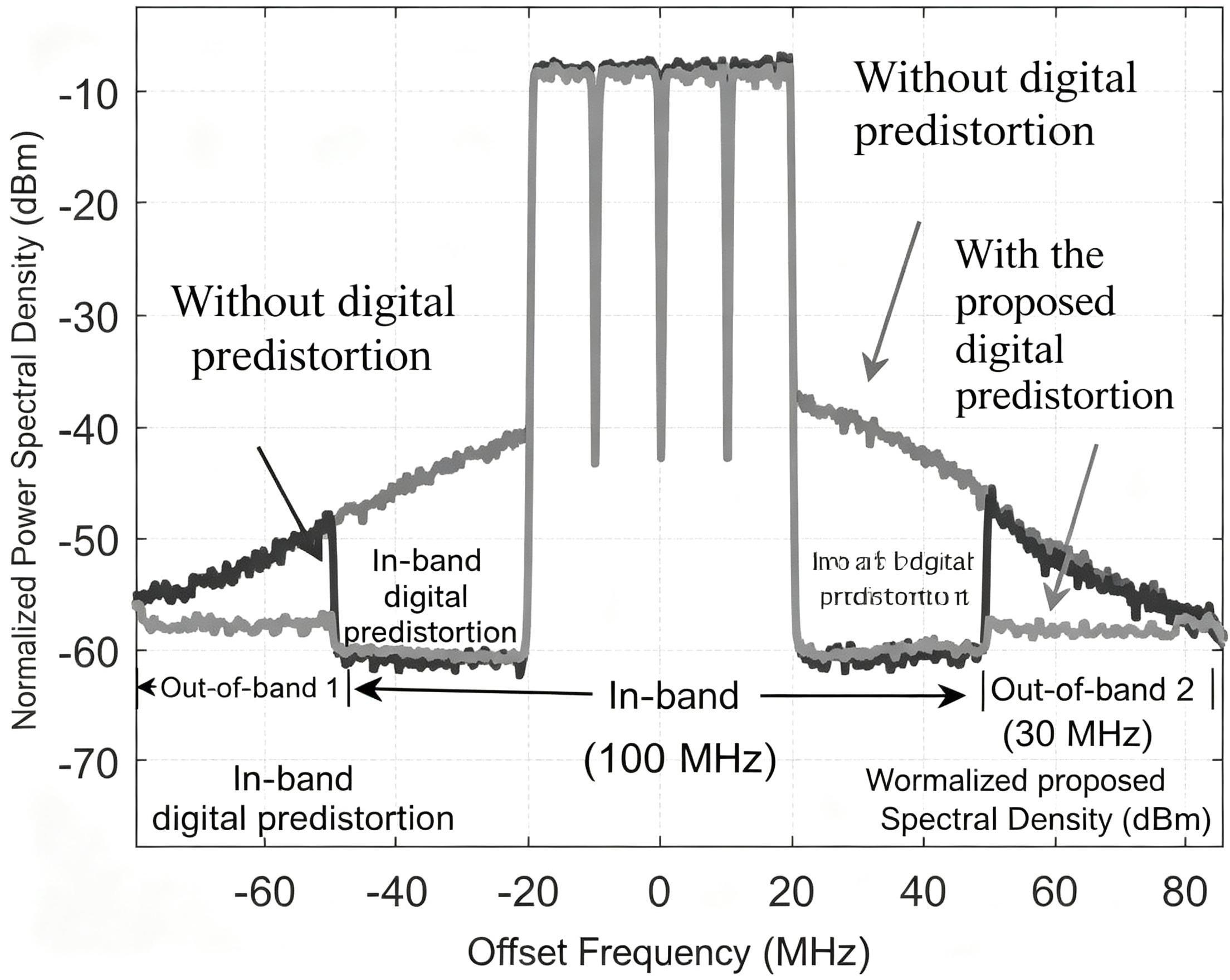
Out-of-band distortion: stray signals interfere with other frequency bands, messing with the whole communication network.
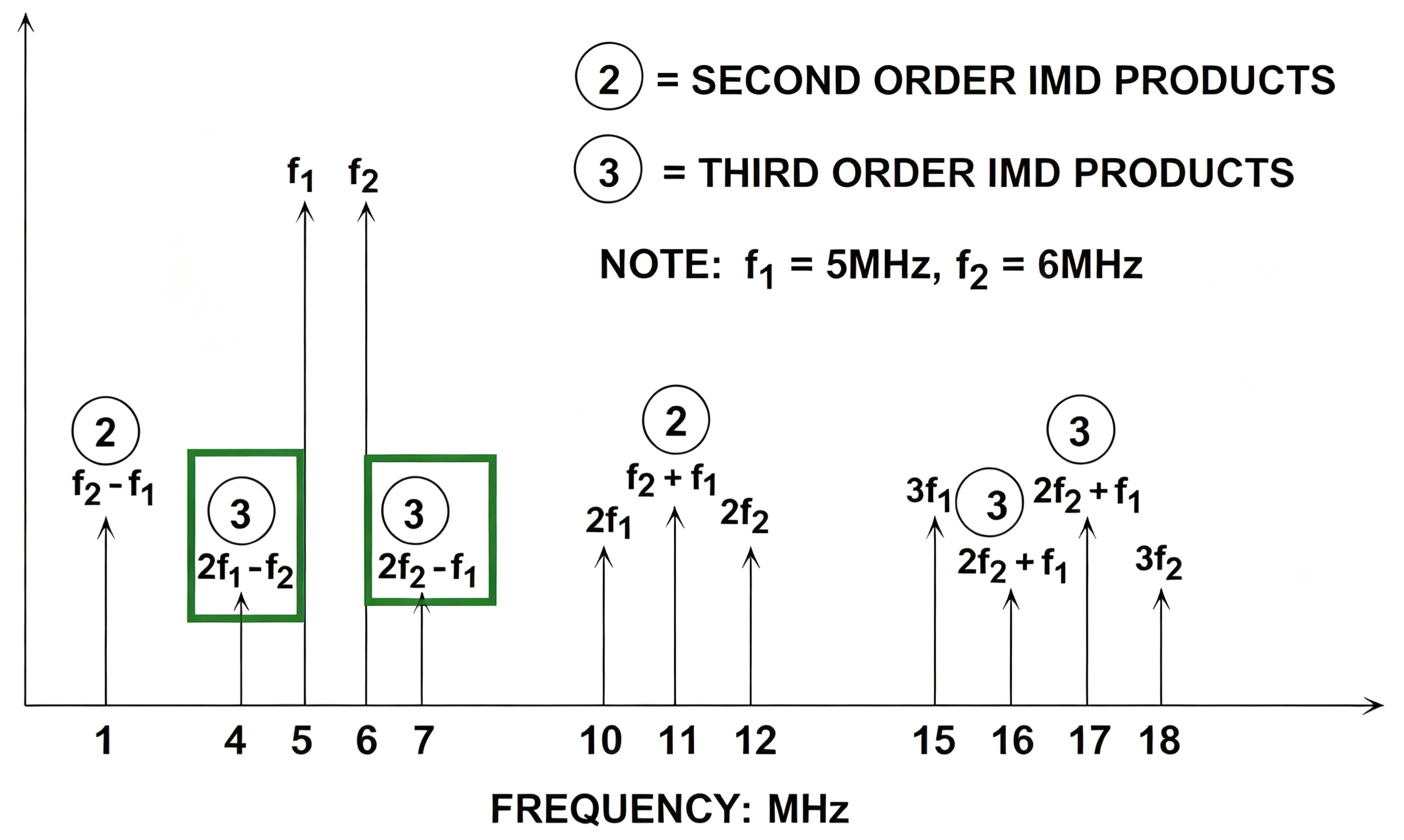
Amplifier output distortion mainly includes harmonic distortion and intermodulation distortion. Harmonic distortion can be effectively filtered out, while the third-order intermodulation distortion (IMD3) near the carrier frequency is the key factor affecting system linearity. The value of the third-order intermodulation parameter can directly indicate how good or bad the amplifier’s linear performance is.
Mainstream Linearization Techniques and Comparisons
To improve amplifier nonlinearity, the industry commonly uses four linearization schemes, and the pros and cons of each are as follows:
Power back-off method: easy to operate, but it sacrifices amplifier efficiency and slightly increases hardware costs;
Negative feedback method: introduces noise, lowers system signal-to-noise ratio, and affects circuit response speed and stability;
Pre-distortion method: low cost and high efficiency, but the improvement in linearity is limited;
Feedforward method: complex circuit structure and higher overall cost, but in theory, it can completely suppress distortion signals and offers the best linearity improvement.
Basic Principles of Feedforward Technology
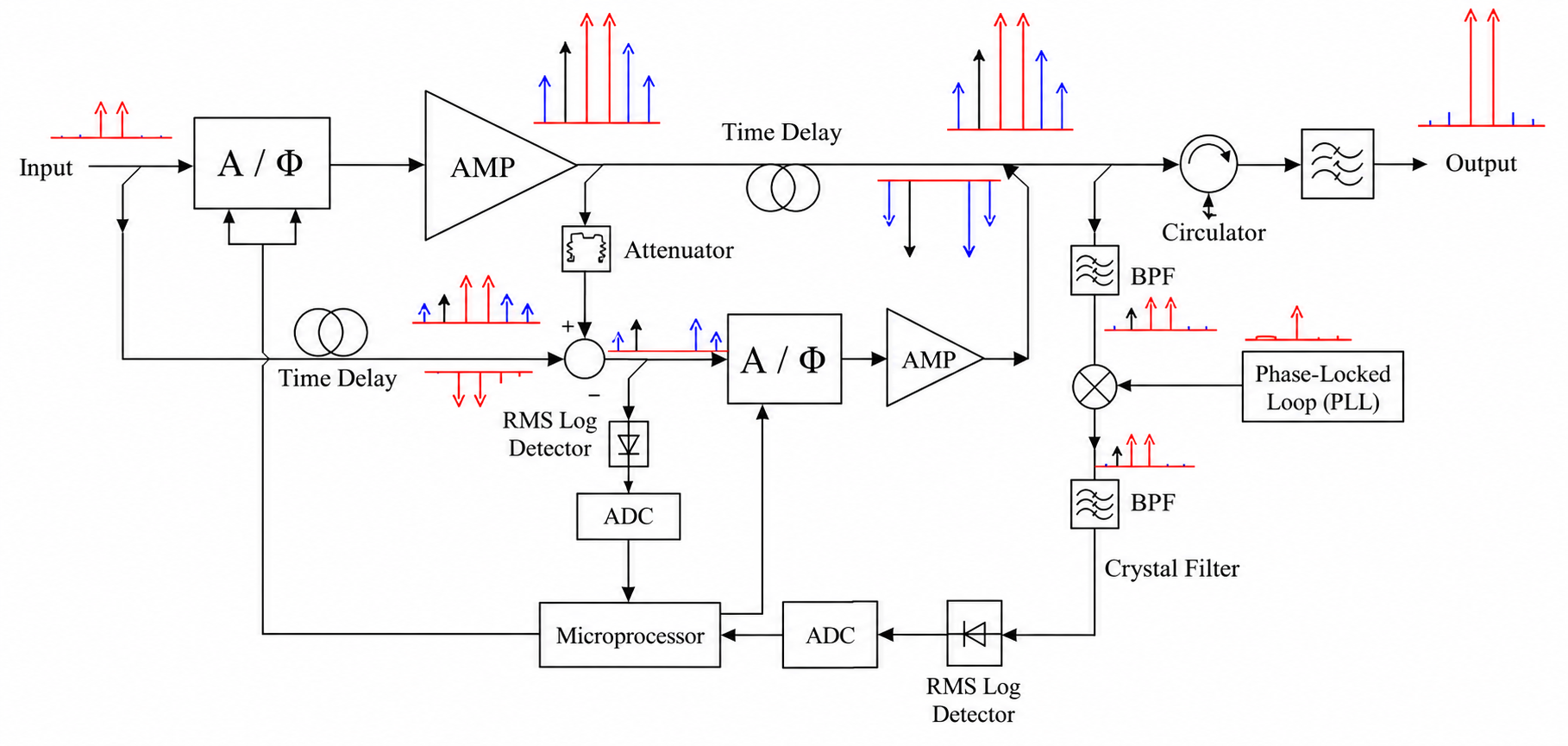
A feedforward amplifier suppresses distortion through two loops: a signal cancellation loop and an error cancellation loop. The main idea is to separate the main signal from the distortion component, then cancel out the distortion component, which improves the overall linearity.
Signal Cancellation Loop
The input RF signal is split into two paths by a coupler:
The upper path signal goes into the main power amplifier (MPA) for amplification, and part of the signal is coupled to the lower path;
The lower path signal, after vector modulation and delay line processing, is sent into the coupler;
The two signals are then subtracted in equal amplitude and opposite phase, canceling out the clean main signal and finally isolating distortion signals like intermodulation and harmonics.
Error Compensation Loop
After the main signal is cleaned up through signal cancellation, it’s sent into the output coupler via a delay line;
The distortion signal extracted by the signal cancellation loop is vector-modulated and sent to the error power amplifier (EPA) for amplification;
The amplified distortion signal and the main signal are then canceled out evenly in the output coupler to completely remove the distortion components, resulting in a highly linear RF signal at the output.
Typical Circuit Architecture
A complete feedforward amplifier consists of several key components, including couplers, circulators, delay lines, vector modulators, main driver amplifiers, and Doherty amplifiers. The circuit is divided into two primary loops. It uses multiple sets of delay lines and vector modulators to achieve precise amplitude, phase, and delay matching. This enables multi-stage signal cancellation and significantly improves the linearity of the power amplifier.
Key Parameter Analysis of Feedforward Technology
The distortion suppression effect of the feedforward loop is mainly determined by three key parameters: amplitude, phase, and delay. Here are the core parameters defined:
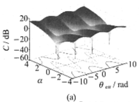
C: Loop suppression parameter; the smaller the C value, the better the suppression of signal and distortion.
d: Relative delay mismatch coefficient.
Impact of Amplitude and Phase Mismatch
With the delay perfectly matched, amplitude and phase imbalances directly worsen the loop suppression capability:
When the two branches have equal amplitude and perfectly opposite phases, the signal at the central dip can be completely canceled, making the theoretical C value negative infinity, which is the best working state.
If the amplitude mismatch factor deviates from the ideal value, the loop suppression parameter C deteriorates quickly, showing that the feedforward loop is highly sensitive to amplitude matching. Phase differences affect C periodically, and you can optimize the parameter by adjusting the branch phases.
Impact of Delayed Mismatches
The delay matching determines the operating bandwidth of the loop, which is key for wideband applications:
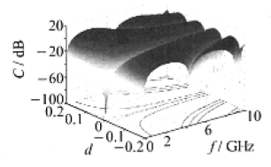
When the relative delay mismatch is completely consistent, optimal suppression can be achieved across the entire frequency range;
Otherwise, the loop’s suppression capability varies significantly at different frequencies. The larger the value of d, the more dramatically C changes with frequency, and the narrower the loop’s usable bandwidth becomes.
Delay mismatch is a key factor limiting the working bandwidth of the feedforward power amplifier, so branch delay differences must be strictly controlled during design and debugging.
Feedforward Loop Debugging and Testing Guidelines
Feedforward is divided into Loop 1 (signal cancellation loop) and Loop 2 (error cancellation loop). You need to debug it step by step, strictly controlling parameters like gain, delay, and standing wave.
Loop 1 Debugging Requirements
Under large-signal conditions, optimize the open-loop linearity of the active loop, requiring the open-loop third-order intermodulation to be ≤ -40dBc, and reduce the workload on the secondary loop;
Under small-signal conditions, try to flatten the gain flatness of the active loop to ensure the delays of each branch are basically consistent;
The gain flatness and delay variation trends of the passive loop and the active loop must stay synchronized to ensure effective signal cancellation.
Loop 2 Debugging Requirements
In the small-signal state, the active loop gain flatness is ≤0.5dB, and the branch delay difference is kept within 0.5ns;
The passive loop gain flatness is ≤0.3dB, and the delay difference across the entire operating frequency band is ≤0.5ns;
The passive loop input VSWR is optimized to below -15dB; matching adjustments can be done using microstrip lines combined with capacitors and power inductors, and at the same time, the main signal power loss must not increase.
Combination of Feedforward and Predistortion Technologies
Categories and Principles of Pre-Distortion Technology
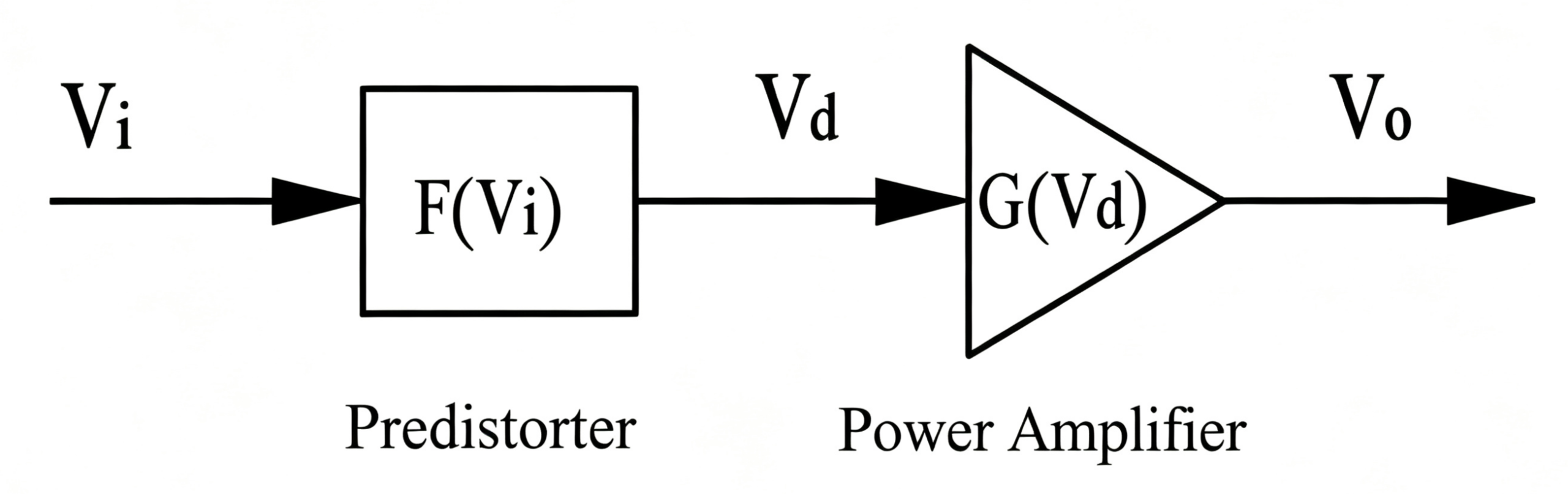
Predistortion is one of the mainstream linearization techniques, and the classifications are as follows:
By signal chain location: RF predistortion, IF predistortion, baseband predistortion;
By implementation method: analog predistortion, digital predistortion.
Basic principle: A predistortion network is connected to the front end of the amplifier. The distortion generated by this network cancels out the nonlinear characteristics of the amplifier, thus compensating for the overall distortion of the device. Analog predistortion can be built using components like diodes or FETs to create a distortion circuit, and adaptive control circuits can also be added to counter parameter drift caused by the environment or component aging.
Pros and Cons of Pre-distortion Technology
Pros: The circuit structure is simple and cheap; no stability issues; works well at high frequencies with a wide bandwidth; the overall efficiency of the amplifier is high.
Cons: Limited ability to improve linearity; hard to cancel high-order distortion components, and may even worsen high-order performance; poor environmental adaptability, usually needs to be used with adaptive circuitry.
Hybrid Application Solution
Combining predistortion technology with feedforward technology is the current mainstream optimization approach: by adding a predistortion circuit before the main amplifier, it can pre-compensate for some nonlinear distortion, greatly reducing the linear optimization pressure on the feedforward loop, while also lowering the power capacity requirements for the error amplifier, balancing linearity, cost, and efficiency.
Conclusion
Feedforward technology plays a vital role in reducing RF power amplifier distortion and enhancing signal quality. When combined with predistortion, it delivers superior performance for today’s high-power, wideband communication systems.
ZR Hi-Tech offers customized RF power amplifiers and microwave solutions tailored to your application. Contact us today to learn more.



