
Newsroom
RF Combiner vs Power Divider vs Coupler vs 3 dB Bridge: What’s the Difference?
In wireless communication and broadcasting systems, properly allocating and combining signals is key to ensuring signal quality and system efficiency. Power divider, combiners, and couplers are three commonly used devices for achieving this. Next, we’ll go over the functions, use cases, and technical details of each device in detail.
Power Divider
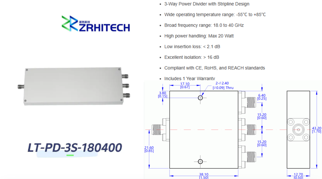
A power divider, also called a power splitter, divides one input signal into multiple output signals. It is widely used in RF systems. In base stations, power dividers can distribute signals received by the antenna to multiple processing devices.
Common types include 2-way, 3-way, and 4-way power dividers. Each output typically has a fixed splitting loss. For example, a 2-way divider has a theoretical splitting loss of 3 dB per output.
Combiner
The role of a combiner is to merge multiple input signals into a single output. This kind of device is often used in multi-channel systems to reduce the number of devices and optimize signal paths.
Combiners can be divided into cavity combiners and hybrid combiners. Cavity combiners are commonly used in high-power applications. They offer high power-handling capability and good isolation between channels.
Hybrid combiners are more compact and flexible. They are often used in RF systems where multiple signals need to be combined with controlled amplitude and phase relationships.
When selecting a combiner, engineers should consider factors such as frequency range, insertion loss, isolation, power handling, and port configuration. These parameters directly affect the efficiency and reliability of the RF system.
Combiners Are Divided Into Same-frequency Combiners and Different-frequency Combiners
A co-frequency combiner can also be called a 3dB bridge. It has 2 ports for input and 2 ports for output. When used as a combiner, one of the output ports is connected to a matched load. It’s mainly used for combining multiple signals and improving the efficiency of the output signal.
In network coverage systems, it’s used for combining signals of the same system and serves the purpose of combining same-frequency signals. It can act as a combiner using a Wilkinson power divider or a resistive power divider. The insertion loss is high, and the selectivity isn’t great.
A diplexer is used to combine signals of different frequency bands. For example, for GPS L1 and L2 bands, you need to combine the signals of these two bands. Since the frequency bands are fairly close, you can use a power divider approach, but for combining, you can only use Wilkins or resistive types, with an operating bandwidth that covers both bands. The preferred solution is a filter-based approach.
Coupler
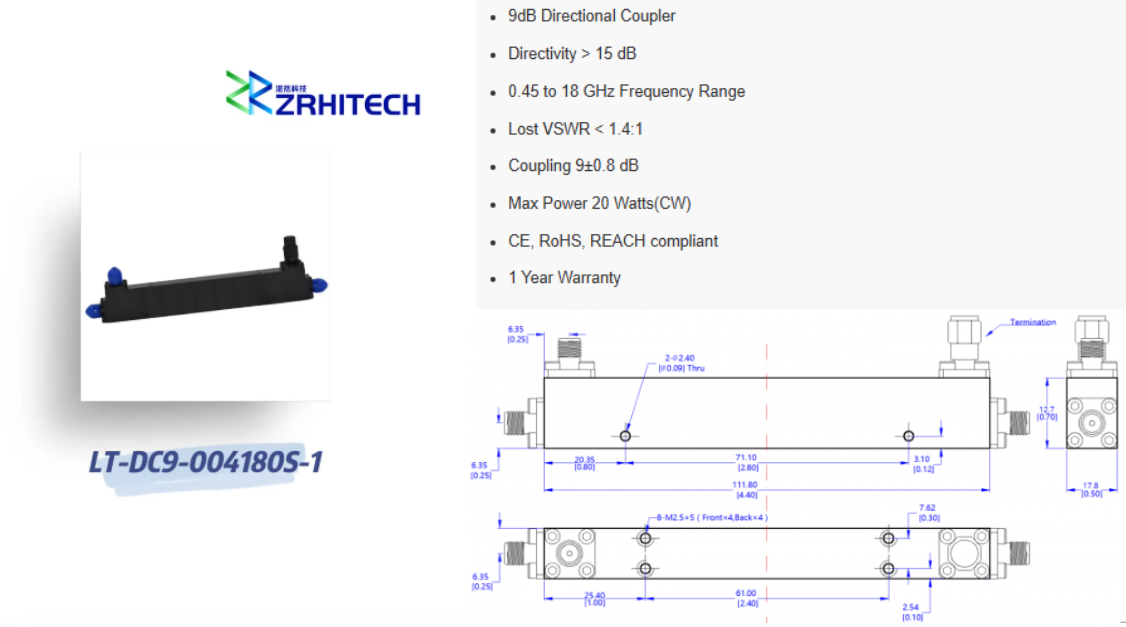
A coupler is used to proportionally split a single input signal into multiple output ports. A coupler has three ports: the input port, the thru port, and the coupled port, with the coupled port having some attenuation relative to the thru port.
Directional couplers are mainly used for power monitoring, stabilizing source output power, power combining, signal source isolation, and reflection coefficient testing. The coupled port of a 3dB coupler splits 50% of the power, a 6dB coupler splits 25%, and a 10dB coupler splits 10%.
Use Case
1. Antenna distribution systems: When a transmitter needs to connect to multiple antennas, an in-phase combiner can distribute the signal to different antennas, allowing them to operate simultaneously on the same frequency band.
2. RF front-end modules: In RF front-end modules, an in-phase combiner can let multiple transceiver modules share the same antenna, which helps reduce system space and costs.
3. Signal analysis instruments: An in-phase combiner can merge multiple input signals into one, making it easier for further processing and analysis.
Technical Specifications of The Power Divider
- Insertion loss: This usually refers to the power loss when a signal passes through a power splitter. For common splitters, like a 3dB splitter, the loss at each output port is about 3dB.
- Isolation: This refers to how well one output port is isolated from another. High isolation helps reduce signal interference between ports.
- Frequency range: The splitter should cover the operating frequency range, and different designs might be made for specific frequency bands.
- Phase balance: The consistency of the output signal phases is crucial for ensuring signal synchronization.
- Power handling: The maximum power the splitter can handle.
Technical Specifications of The Combiner
- Insertion loss: The power loss when a signal passes through a combiner. For example, the insertion loss of a 4-channel combiner is usually less than 3.6dB, and for an 8-channel combiner, it’s usually less than 4.0dB.
- Channel isolation: How well the channels in a combiner are isolated from each other, usually required to be above 80dB to prevent the signals from interfering with each other.
- Isolation between output and input ports: Also usually required to be above 80dB, ensuring that the input signal doesn’t flow back to other ports.
- Frequency drift: The change in frequency as the equipment ages, usually shouldn’t exceed 3ppm after a year.
- Input VSWR: Less than 1.5dB, this indicates the level of signal reflection, with a lower VSWR meaning more efficient signal transmission.
Technical Specifications of The Coupler
- Coupling Value: The proportion of input signal power allocated to the coupled port, common values include 5dB, 10dB, etc. The higher the coupling value, the weaker the signal at the coupled port.
- Insertion Loss: The signal loss at the through port. Although theoretically there should be no loss at the through port, in practice there might be a small amount of loss.
- Isolation: The isolation between the coupled port and the input/through ports, ensuring independent signal transmission.
- Frequency Response: The performance consistency of the coupler across the operating frequency range, making sure the coupling effect is consistent throughout the band.
Conclusion
Power dividers, combiners, and couplers are foundational passive building blocks for wireless communication and broadcasting systems. Each device serves distinct roles: power dividers split signals, combiners merge multi‑channel signals, and directional couplers enable power sampling and monitoring.
Selecting the right component goes far beyond checking frequency range and port count. Engineers must carefully evaluate critical specifications including insertion loss, isolation, power‑handling capability, VSWR, phase balance and frequency response. Poor component selection will introduce signal interference, extra power loss and reduce overall system reliability.
Whether you work on antenna distribution systems, RF front‑end hardware or signal‑test instruments, matching device performance to real‑world application requirements is essential for stable system operation.
If you need standard or custom‑designed RF power dividers, combiners and couplers for your project, contact ZR Hi‑tech. Our engineering team can support your component selection and customized RF solution development.



