
Newsroom
A Deep Dive into Directional Couplers: The ‘Power Stethoscope’ of RF Links
First Get The Essence: a directional coupler ≠ a regular signal splitter
A directional coupler is a passive coupling device that has directional selectivity. It can pick off the forward (or reverse) RF signals from the main transmission link at a fixed ratio, while strongly suppressing signals in the opposite direction. Simply put, it only ‘collects’ signals in one direction and isn’t affected by signals reflecting back the other way.
The main difference between it and regular power splitters or resistor voltage sampling is in three core features: directional transmission and one-way sampling.
This is the most essential feature of a directional coupler. A high-quality coupler couples the forward signal accurately while strongly suppressing the reverse signal, so you can independently measure the incident and reflected power, and then calculate the standing wave ratio and matching status. Ordinary splitters or resistive dividers don’t have directionality, and the forward and reverse signals get mixed together, so you can only measure the total power and can’t tell the transmission direction.
The Main Line Has Low Loss and Doesn’t Affect The Main Link
High Isolation, Ports Don’t Interfere with Each Other
There’s good isolation between the coupled port, isolated port, and through port. Changes in the load at the coupled port won’t interfere with the main link, and signals at the isolated port won’t feed back into the coupled port, ensuring accurate monitoring and stability of the main system.
To give a simple analogy: regular branch sampling is like drilling a hole in a water pipe—water flows in and out, and you can’t tell the direction. But a directional coupler is like a one-way flow meter; it accurately measures the water flowing in the forward direction, and backflow barely affects the measurement. This way, you can monitor flow in real time without disrupting the main supply.
More Than Just Sampling: 4 Core Functions of Directional Coupler
1. Core Function: Forward/Reverse Power Online Monitoring
This is the classic use of directional coupler. They are connected in series in the transmission link to separately take out the incident and reflected power. With a detector, you can monitor the output power and antenna matching in real time, which is the basis for closed-loop control in transmission systems.
2. Protection Function: VSWR Detection and Fault Alarm
By monitoring the reflected power, the load standing wave ratio can be calculated in real time. When the antenna is shorted, open, or severely mismatched, the reflected power spikes, and the system can trigger actions like reducing power or shutting down to prevent the power amplifier from being damaged by reflected power. This is essential in high-power transmission systems.
3. Calibration Function: Link Signal Sampling and Calibration
A small portion of the signal is taken from the main link and fed into a spectrum analyzer, power meter, or detection circuit for spectrum monitoring, frequency locking, and gain calibration. This doesn’t affect the main path and is widely used in test instruments and smart RF systems.
4. Extended Function: Signal Distribution and Power Combining
Specially structured directional couplers can also be used for low-power signal distribution, multi-link coupling feeds, or to achieve specific power distribution ratios in phased array feed networks, serving both monitoring and distribution purposes.
8 Key Parameters You Must Check When Choosing A Model: Don’t Just Look at The Coupling
A lot of people choose directional couplers just by asking ‘how many dB coupling, what frequency,’ which is a classic beginner mistake. Even if two coaxial couplers both have 30dB coupling, differences in directivity, power handling, and main line loss will directly affect monitoring accuracy and system reliability.
1. Coupling factor (the most basic nominal parameter)
Refers to the ratio of the main line input power to the output power at the coupled port, measured in dB. The higher the value, the smaller the coupled signal.
Common specs are 6dB, 10dB, 20dB, 30dB, and 40dB.
How to pick one: choose based on the signal level your detection circuit needs. For power monitoring, 20~30dB is common; for small signal sampling, 10~20dB works. If the coupling factor is too low, you’ll waste too much main line power; if it’s too high, your detection might not be sensitive enough.
2.Directivity (the key metric of a directional coupler)
3. Isolation level
It refers to the ratio of the input power on the main line in the reverse direction to the output power at the coupled port, measured in dB.
Directivity = Isolation – Coupling, and the two are basically just different ways of describing the same characteristic.
Isolation directly shows how well the reverse signal is suppressed, and it’s a key factor in measuring reflected power and in dual-directional coupler setups.
4.Insertion loss (main line through loss)
The loss from the main input to the through output contains two parts.
They are inherent loss from conductors and dielectrics, plus power diverted via coupling. Generally, higher coupling corresponds to lower extra loss on the main transmission line. Transmit chains typically select low-loss couplers to avoid wasting RF power.
For receive chains, engineers need to evaluate how this loss degrades the system noise figure.
5. Standing Wave Ratio / Return Loss
The impedance matching indicators for all ports need to be checked, both the pass-through port and the coupling port.
For regular industrial grade, it should be ≤1.5; for high-quality military grade, ≤1.2.
A high VSWR on the main line can directly worsen the matching of the whole transmission chain, making the power amplifier unstable. A high VSWR on the coupling port can reduce directivity and affect measurement accuracy.
6. Power capacity (hard spec for the transmitter)
The maximum continuous wave power that the main path can handle for a long time is closely related to the operating frequency and ambient temperature.
The pattern is: the higher the frequency, the lower the power capacity; the higher the ambient temperature, the more you need to derate.
Selection principle: you must leave a margin of 1.5 to 2 times the actual maximum power, and in high-power scenarios, small-power microstrip couplers must not be used instead of coaxial couplers.
7. Coupling Flatness
Within the working frequency range, the fluctuation range of coupling, measured in dB, the smaller the fluctuation, the better the flatness.
Broadband systems require high flatness; otherwise, detection levels vary a lot at different frequencies, making calibration difficult.
Narrowband systems can be a bit more relaxed, but broadband testing and monitoring systems need to pay special attention.
8. Port Types and Installation Methods
Ports: Common types include SMA, N-type, 2.92mm, etc., and they need to match the system interface.
Installation: Options include flange mounting, threaded mounting, surface mounting, board-level mounting, etc., choose as needed.
A bidirectional coupler has both forward and reverse coupling ports, so it can monitor incident and reflected signals at the same time, making it a common solution for power detection.
6 Core Application Scenarios: Military and Industrial Fully Implemented
Directional couplers are standard components in all RF systems with power monitoring and closed-loop control. The examples below are typical terminals in the military and industrial fields, and they match your product lineup very well.
1. Radar and Electronic Warfare Systems
Radar transmitters need to monitor output power and antenna standing waves in real time to prevent antenna mismatches from burning out the transmission components. Electronic countermeasure systems use couplers to monitor interference signal power and achieve closed-loop power control.
Typical terminals include active phased array radars, early warning radars, vehicle-mounted fire control radars, and electronic warfare jamming aircraft.
Corresponding products are high-power coaxial/waveguide directional couplers and microstrip band couplers, often used together with filters and power dividers.
The key requirements are high power, high directivity, wide temperature reliability, and amplitude-phase stability.
2. Industrial Radar and Sensor Front End
The transmit links of millimeter-wave radar and level radar sample the transmit power via couplers and work with detection circuits to complete power calibration and self-checks; some MIMO radars also use couplers to achieve channel power balancing.
Typical applications include 24G/77G traffic speed radars, level meters for liquid levels, security perimeter radars, and river flow radars.
Corresponding products are microstrip directional couplers and surface-mount couplers. The key requirements are small size, good consistency, and high batch stability.
3. Communication Private Network and Base Station System
The transmit path of base stations, repeater stations, and private network radios uses series directional couplers for power detection and standing wave protection. Indoor distribution systems also use couplers to manage power distribution and monitoring across different areas.
Typical devices include mobile communication base stations, private network data radios, fiber optic repeaters, and broadcast TV transmitters. Corresponding products are coaxial directional couplers and broadband couplers, with outdoor versions needing to be waterproof and weather-resistant.
Key requirements are low loss, high isolation, and long-term operational stability.
4. RF Test Measurement Instruments
Test equipment like vector network analyzers, spectrum analyzers, and power meters heavily use high-precision directional couplers inside to sample signals, measure reflections, and test S-parameters. They’re the core passive components of testing instruments.
Typical applications include vector network analyzers, RF power meters, automated production test systems, and calibration devices. Corresponding products are high-precision coaxial or stripline directional couplers.
The main requirements are high directivity, low VSWR, good flatness, high repeatability, and long lifespan.
5. Semiconductors and Industrial RF Power Supplies
RF power supplies for semiconductor etching and coating equipment, as well as industrial microwave heating equipment, monitor forward and reflected power through directional couplers. Paired with impedance tuners, they achieve automatic tuning to keep the plasma stable.
Typical end uses include semiconductor PECVD/etching equipment RF power supplies, plasma cleaners, and industrial microwave heating devices.
Corresponding products are high-power coaxial directional couplers, often used with glass insulators and RF cable assemblies. Core requirements: high power, high reliability, heat resistance, and suitability for long-term continuous operation.
6. Satellite Navigation and Anti-Jamming System
Beidou anti-jamming terminals and satellite communication receiving systems sample link signals through couplers for gain calibration and channel equalization, ensuring amplitude and phase consistency across multiple channels.
Typical terminals include Beidou anti-jamming receivers, satellite communication ground stations, and military vehicle navigation antennas.
Corresponding products are low-loss microstrip/coaxial directional couplers, with core requirements being low loss, high isolation, and phase stability.
Conclusion
Directional couplers are more than simple RF signal sampling components. They play an important role in forward and reverse power monitoring, VSWR detection, signal calibration, and RF power control. Their low insertion loss, high isolation, and directional selectivity make them essential in radar, communication systems, RF test equipment, industrial RF power supplies, satellite navigation, and other high-performance RF applications.
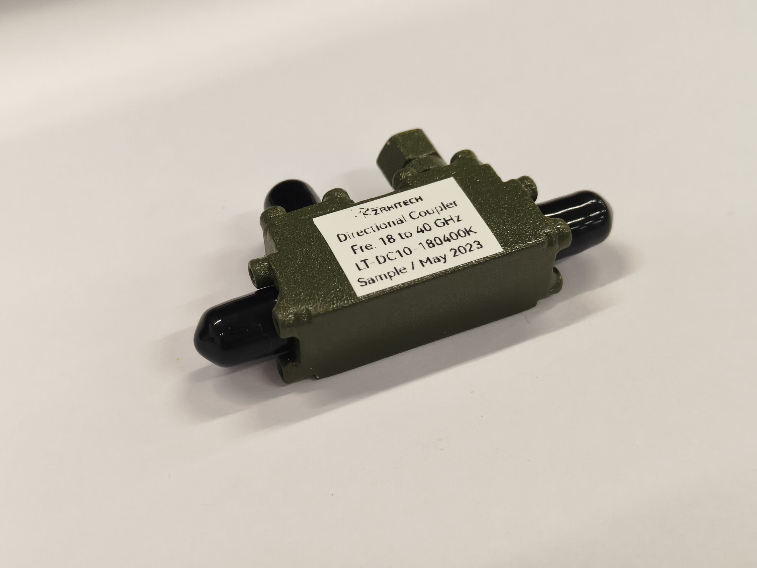
When selecting a directional coupler, engineers should look beyond coupling factor and operating frequency. Directivity, isolation, insertion loss, VSWR, power capacity, coupling flatness, connector type, and installation method can all affect system performance and long-term reliability. For high-power or precision monitoring applications, choosing the right specifications is especially important.
ZR Hi-Tech provides RF passive components designed for demanding communication, radar, test and measurement, satellite, and industrial applications. Whether you need a standard directional coupler or a customized solution with specific frequency, coupling, power handling, connector, or mechanical requirements, our engineering team can help identify a suitable solution for your RF system.
Contact ZR Hi-Tech to discuss your directional coupler requirements and find the right RF solution for your application.



