
Newsroom
Power Dividers in Advanced RF Systems: Core Functions & Key Applications
A power divider is a passive RF and microwave component that directs and combines signal energy. It is a multi-port network based on the reciprocity theorem. In its most common mode, it divides the power of one input signal into multiple outputs with a defined power ratio. When used in reverse, it combines multiple input signals into a single output. Thanks to these capabilities, power dividers are widely used in wireless communications, radar systems, and RF test and measurement applications.
Core Principles and Parameters of a Power Divider
A power divider operates by controlling how electromagnetic waves propagate through its internal circuit structure. Its electrical performance is characterized by scattering parameters (S-parameters). When an RF signal enters the input port, a network of transmission lines and impedance-matching elements distributes the signal power to the output ports.
In a Wilkinson power divider, quarter-wavelength transmission lines perform the impedance transformation needed for equal power division. Meanwhile, isolation resistors dissipate reverse signals between the output ports, ensuring excellent isolation and minimizing signal interaction.
To judge the performance of a power divider, we need to pay attention to these four key indicators:
Insertion Loss
Includes inherent theoretical distribution loss and additional loss caused by conductor and dielectric losses. It determines how much the signal power decreases as it passes through the device and is a key factor affecting system efficiency.
Isolation Level
It shows how much the output ports affect each other—the higher the isolation, the more stable the system is.
Return Loss
It shows how well the port is impedance-matched, which directly affects how much signal gets reflected.
Amplitude and Phase Consistency
This is crucial for systems that rely on the coherence of multiple signals.
Mainstream Product Types and Technical Features
Faced with different application scenarios, power dividers have developed several main types, each with its own advantages.
Microstrip Power Divider
The microstrip power divider uses printed circuit board technology to make circuits on a dielectric substrate. It has obvious advantages like flexible design, low cost, small size, and easy integration, but its performance is significantly affected by the substrate material, process accuracy, and operating frequency.
As the number of power split paths increases, the design challenges grow sharply. It usually requires cascading multiple stages in a tree structure, which brings a bunch of technical headaches like higher cumulative loss, difficulty in controlling phase consistency, more complex overall layout, and complicated isolation resistor network design. So, high-path-count microstrip power dividers are an important measure of design capability and process level.
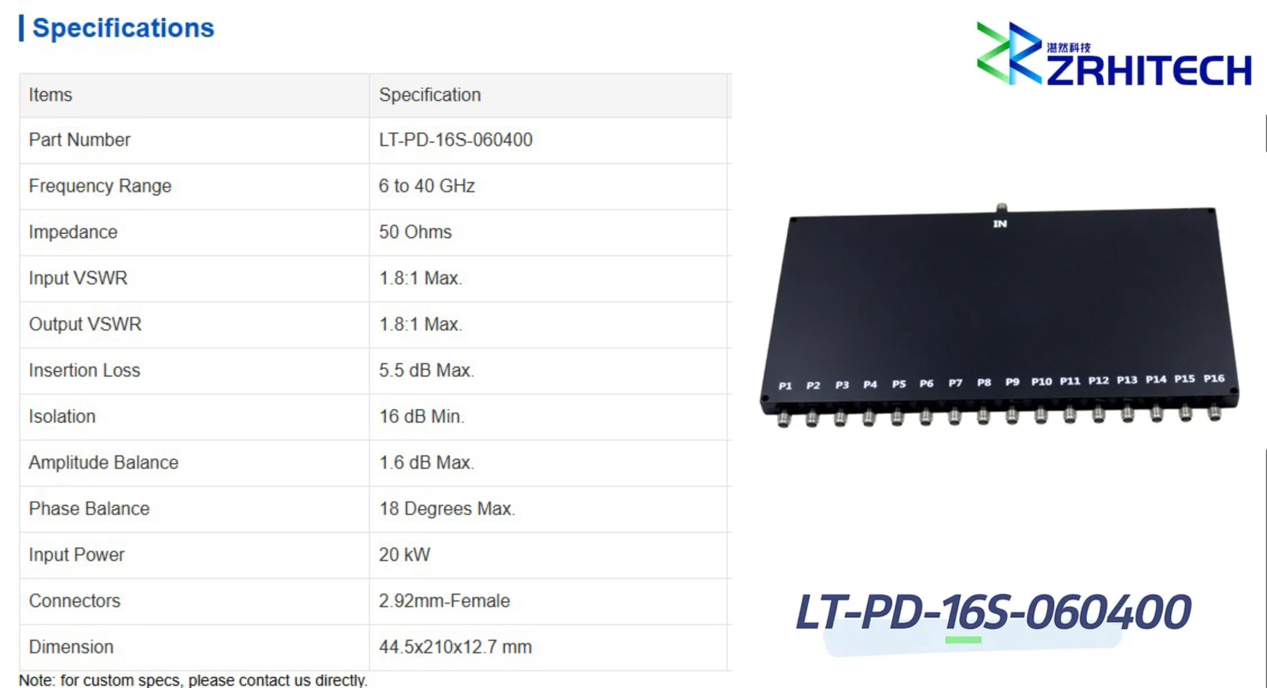
ZR Hi-tech offers ultra-wideband coaxial microstrip power dividers and combiners, covering frequencies from DC to 50GHz. They come in 2 to 16 ports, featuring low insertion loss, low VSWR, high isolation, and excellent amplitude and phase consistency. They’re widely used in test equipment, 5G systems, and other cutting-edge fields.
Resistive Power Divider
A resistive power divider is a broadband device made entirely of a resistor network. Its biggest feature is that it can work steadily from DC to very high frequencies. It uses precise resistor value matching to achieve power distribution and impedance matching at each port.
Its drawback is that there’s no isolation between output ports, so any load change on one port will directly affect the others. Plus, the insertion loss is much higher than the theoretical split loss because some of the signal energy gets dissipated as heat in the resistors, which limits its power handling. It’s perfect for test and measurement scenarios that demand really high bandwidth and amplitude consistency, but don’t need much isolation.
Cavity Power Divider
A cavity power divider encloses the circuit structure inside a metal cavity, using cavity resonance and distributed parameters to operate. This design gives it standout advantages like high power capacity, low insertion loss, high quality factor, and stable, reliable performance.
Its drawbacks are mainly that it’s relatively big and heavy, and the manufacturing cost is higher. It’s mainly used in scenarios like macro base stations and high-power indoor distribution systems where there are strict requirements for power and efficiency.
Waveguide Power Divider
Waveguide power dividers use metal waveguides as the transmission medium and are the preferred solution for millimeter waves and other high-frequency bands. They work based on various excitations and distribution structures of electromagnetic waves inside the waveguide. The waveguide structure naturally gives them very low transmission loss and very high power handling capability.
Its drawbacks are also obvious, including being very large, complicated to manufacture, and expensive, usually limited to high-end fields like satellite communications, high-power radar, and research instruments.
Typical Use Cases of a Power Divider
Power dividers are used all over modern RF systems.
In wireless communications, they’re a key part of indoor distribution systems, making sure base station signals are evenly sent to all the antennas in the target area.
In advanced radar systems, especially phased array radar, power dividers work with phase shifters to form complex antenna feed networks, giving thousands of radiating elements precise amplitude and phase signals.
In RF testing and measurement, power dividers let a single signal source feed multiple testing devices at the same time, so you can compare and analyze results together.
Plus, in satellite communication and navigation receivers, they’re used to split signals from one antenna to multiple receiving devices.
ZR Hi-tech Product Advantages and Core Strengths
ZR Hi-tech, with its solid technical foundation, has built a complete range of high-performance power dividers and is dedicated to providing professional solutions for our customers.
Power Divider Product Range: Our microstrip power divider series uses advanced electromagnetic simulation and high-precision manufacturing processes to ensure consistent and superior performance across the entire line, from low to high channels. The resistive power divider series uses high-precision thin-film resistors, guaranteeing amplitude and phase stability across ultra-wide bandwidths.
High Reliability Assurance: All our power divider products follow strict quality standards, undergo comprehensive environmental stress screening and reliability testing, and have fully passed ISO9001 and GJB-9001C military standard certifications.
Deep Customization Service: We have strong custom development capabilities and can offer flexible customization according to specific customer needs, including work frequency band, number of power divider channels, interface types, and mechanical structures.



