Newsroom
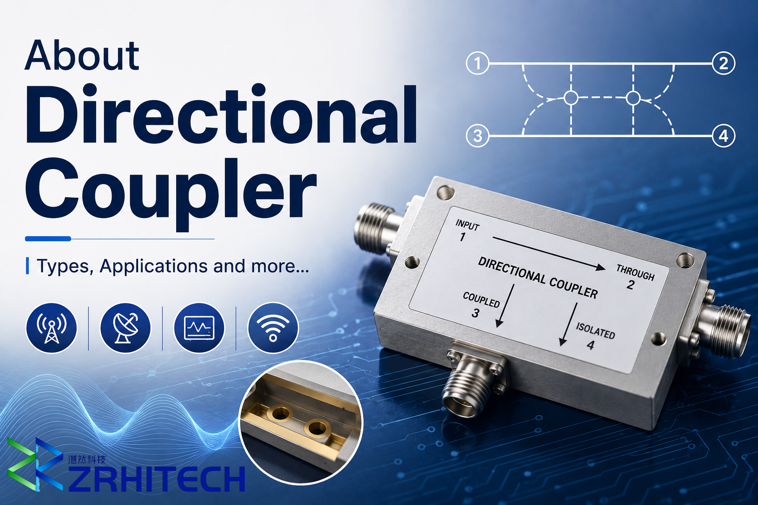
About Directional Coupler | Types, Applications and more…
In the field of radio frequency (RF), power consumption is an extremely important topic. Good RF power management can extend the lifespan and operating time of equipment, while also reducing energy consumption and heat generation.Besides basic baseband power consumption, a significant portion of RF power consumption originates from the power amplifier (PA). Therefore, dynamically managing the PA and input signals to ensure that the transmit power matches the application scenario and performance requirements is crucial. This article introduces one of the key components for RF power management—the directional coupler.
What is a Directional Coupler?
A directional coupler is a general-purpose microwave/millimeter-wave component, a commonly used passive RF device in RF circuit design. A directional power coupling (distribution) element.
A directional coupler is a four-port RF component composed of a main transmission line and a secondary coupled line. Through electromagnetic coupling structures such as gaps, holes, or coupling sections, part of the signal power is transferred from the main line to the coupled line.
The coupled energy is delivered to a specific output port while the opposite port ideally remains isolated. This directional signal-coupling capability enables accurate power monitoring, signal sampling, and RF measurement applications.
If the wave propagation direction in the through line changes to the opposite direction, the output port and the non-output port in the coupled line will also change accordingly. In other words, the power coupling (distribution) is directional, hence the name directional coupler.
What are the Different Types of Directional Coupler?
Directional couplers can be classified into different types according to different classification standards, differing in performance, application scenarios, and design complexity.
1. Classification by Transmission Line Type
- Waveguide Directional Coupler: Utilizes waveguide structures for signal coupling, suitable for high-power, low-loss scenarios, commonly used in radar, satellite communications, and other fields.
- Coaxial Line Directional Coupler: Based on coaxial line transmission, compact in structure, suitable for signal coupling and monitoring in the mid-to-low frequency band.
- Microstrip Line Directional Coupler: Small in size and easy to integrate, commonly used in microwave integrated circuits and miniaturized devices. Such as mobile phones and wireless communication modules.
- Stripline Directional Coupler: Good shielding performance and low radiation loss, suitable for environments with high electromagnetic interference requirements.
2. Classification by Coupling Degree
- Strongly Coupled Directional Coupler: Also known as tightly coupled, with a coupling degree greater than 6dB, suitable for scenarios requiring high power distribution or signal monitoring, such as feedback control of power amplifiers.
- Weakly Coupled Directional Coupler: Also known as loosely coupled, with a coupling degree less than 20dB, commonly used in applications with high directivity requirements such as signal detection and reflected power monitoring.
- Medium-coupling Directional Couplers: Coupling is between 6dB and 20dB, balancing power distribution and signal monitoring functions.
3. Classification by signal output direction
- Co-directional Directional Couplers: The signal output direction at the coupled end is the same as the input direction, such as branch-line directional couplers.
- Reverse-directional Couplers: The signal output direction at the coupled end is opposite to the input direction, such as coupled-line directional couplers.
4. Classification by coupling mechanism
- Pinhole-coupled Directional Couplers: Signal coupling is achieved through pinholes in the waveguide walls, suitable for narrowband or specific frequency range applications.
- Parallel-coupled Directional Couplers: Utilize electromagnetic coupling between two parallel transmission lines; simple structure, suitable for broadband applications.
- Branch-coupled Directional Couplers: Couple the main line signal to the secondary line through a branch line, enabling power distribution and signal monitoring functions.
- Matched Double-T Directional Couplers: Based on a double-T network structure, possessing good directivity and isolation, commonly used for signal synthesis and distribution.
5. Classification by Function
- Single-directional Coupler: A three-port device that transmits signals in only one direction, commonly used for power monitoring and protection of transmit links.
- Bidirectional Coupler: A four-port device that can monitor both forward and reverse signals simultaneously, suitable for scenarios requiring bidirectional power monitoring.
- Dual-directional Coupler: Composed of two single-directional couplers, offering higher isolation and directivity, suitable for high-performance systems.
The Features of Directional Coupler
An important point to note is that the coupling provided by the directional coupler directly affects the theoretical minimum insertion loss of the main transmission path. The smaller the coupling at the port, the lower the insertion loss.
Typically, the rated power level of the coupling port is lower than the rated power level of the main transmission path. When the difference between the main transmission path power and the coupling strength exceeds the power handling capacity of the coupling port, a failure may occur.
Generally, a three-port directional coupler with precision internal matching termination has higher directionality than a four-port directional coupler with external termination. Another factor to consider is the termination type of the directional coupler’s termination port:
- If the termination resistance is set to be equal to the inherent impedance of the transmission line (typically 50Ω), the energy at that termination port can be absorbed with minimal reflection.
- When the termination port is short-circuited or open-circuited, or mismatched with the characteristic impedance of the transmission line. The energy at that port will be reflected back to the main transmission path.
- When the power at the termination port exceeds the power limit of the terminator, a failure may occur. This situation becomes particularly bad when a matched termination port fails and becomes a reflective load, resulting in destructive power levels within the main transmission path.
Most directional couplers are designed with DC-grounded ports and therefore block DC current. However, some models are specifically engineered to support DC pass-through operation.
When using a DC-pass directional coupler, the DC current must not exceed the manufacturer’s rated limit. Excessive current can generate additional heat due to resistive losses, potentially affecting termination performance and long-term device reliability.
Proper current management is essential to ensure stable operation and maintain the coupler’s RF performance.
To meet target performance, all ports of a dual directional coupler (or bidirectional coupler) must be grounded, and the grounding quality and connected loads must be matched to the port impedance of the directional coupler.
How Many Ports Does a Directional Coupler Have? the Ports’ Names
A directional coupler is a four-port device, with each port matched. These four ports are typically labeled Port 1, Port 2, Port 3, and Port 4, each serving a different function.
1. Input Port (Port 1)
- Function: The input port is the signal source for the directional coupler, used to receive the microwave signal to be processed.
- Signal Flow: After entering the directional coupler from the input port, the signal is partially coupled to the coupling end and the inverting output end, while most of the signal continues to propagate along the straight-through line.
- Importance: The performance of the input port directly affects the overall performance of the directional coupler. Therefore, its design must consider factors such as signal frequency, power, and VSWR.
2. Coupling Port (Port 2)
- Function: The coupling port is used to output the signal coupled from the input port. The amplitude of the coupled signal is usually a certain proportion of the input signal amplitude. This proportion depends on the coupler design.
- Signal Flow: The signal output from the coupling port is a portion of the input signal, coupled from the straight-through line to the coupling line through the coupling mechanism.
- Applications: The signal output from the coupling port is commonly used in power monitoring, gain control, and other applications.
3. Reverse Port (Port 3)
- Function: The reverse port is typically used to detect the reverse component of the input signal to evaluate the isolation performance of the directional coupler. Ideally, the signal at this port should be very small to ensure minimal interference.
- Signal Flow: When the propagation direction of the wave in the straight-through line changes, the output port with power and the port without power output in the coupling line also change accordingly. The reverse port is used to receive and detect the reverse signal in this process.
- Importance: The performance of the reverse port directly reflects the isolation and directivity of the directional coupler. Good isolation and directivity are crucial for ensuring effective signal coupling and minimizing interference.
4. Output Port (Port 4)
- Function: The output port is used to output the uncoupled signal, i.e., the main signal component of the input signal. This port outputs the direct transmission portion of the input signal through the coupler, without coupling.
- Signal Flow: Most of the signal, after entering the directional coupler from the input port, will travel along the straight-through line to the output port.
- Application: The signal output from the output port is the main output signal of the directional coupler, and it is often used in signal transmission, amplification and other applications.
The Main Technical Parameters of Directional Coupler
The main technical specifications of directional couplers include coupling strength, directivity, isolation, VSWR, insertion loss, and operating bandwidth. These specifications collectively determine the performance and application range of the directional coupler.
1. Coupling Strength (C)
- Definition: Coupling strength is the ratio in decibels between the output power at the coupled port and the input power at the input port. It reflects the coupler’s ability to couple signals.
- Calculation Formula: C = -20lg|s14(dB), where s14 is the isolation coefficient in the scattering matrix.
- Importance: Coupling strength is one of the key indicators for evaluating the performance of a directional coupler. directly affecting the signal strength output at the coupled port.
2. Directivity (D)
- Definition: Directivity is the ratio in decibels between the output power at the coupled port and the output power at the reverse port. It reflects the selectivity of the directional coupler for the direction of signal coupling.
- Calculation Formula: D = 20lgs14/s13(dB), where s14 is the isolation coefficient and s13 is the coupling coefficient.
- Importance: Coupling strength is one of the key indicators for evaluating the performance of a directional coupler, directly affecting the signal strength output from the coupling port.
2. Directivity (D)
- Definition: Directivity refers to the ratio in decibels of the output power at the coupling port to the output power at the reverse port. It reflects the selectivity of the directional coupler for the direction of signal coupling.
- Calculation Formula: D = 20lgls14/s13 (dB) where s14 is the isolation coefficient and s13 is the coupling coefficient.
- Importance: Better directivity indicates stronger selectivity of the directional coupler for the direction of signal coupling, and less interference at the reverse port.
3. Isolation
- Definition: Isolation refers to the ratio in decibels of the output power at the reverse port to the input power at the input port. It reflects the directional coupler’s ability to suppress reverse signals.
- Importance: Isolation is an important indicator for evaluating the isolation performance of a directional coupler. Good isolation ensures effective signal coupling and minimizes interference.
4. Standing Wave Ratio (VSWR)
- Definition: VSWR is the ratio of the voltage amplitudes of adjacent antinodes and nodes on a transmission line. It reflects the signal reflection on the transmission line.
- Importance: A lower VSWR indicates less signal reflection on the transmission line and higher transmission efficiency. For directional couplers, a good VSWR ensures stable signal transmission and coupling.
5. Insertion Loss
- Definition: Insertion loss is the signal power loss caused by the introduction of a directional coupler. It reflects the impact of the directional coupler on signal transmission efficiency.
- Importance: A lower insertion loss indicates a smaller impact of the directional coupler on signal transmission efficiency. For applications requiring high-efficiency signal transmission, a low-insertion-loss directional coupler is ideal.
6. Bandwidth
- Definition: Bandwidth refers to the frequency range within which a directional coupler can operate normally. It reflects the frequency response characteristics of the directional coupler.
- Importance: A wider operating bandwidth indicates a wider range of signal frequencies that the directional coupler can handle. For applications requiring the processing of multiple frequency signals, a wideband directional coupler is necessary.
What is a Directional Coupler Used for? The Applications
Directional couplers are widely used in microwave and radar feeder technology and are an important component of many microwave circuits. Their main applications include signal sampling, power monitoring, gain control, source output power stabilization, and frequency sweep testing of transmission and reflection.
In communication systems
They are used for signal monitoring and power distribution. For example, in base stations, a portion of the transmitted signal can be coupled out for power monitoring and signal analysis to ensure that the quality and power of the transmitted signal meet requirements; they can also be used to distribute signals proportionally to different branch circuits, achieving signal splitting.
In radar systems
They are used for the separation and coupling of transmitted and received signals. During transmission, a portion of the transmitted power is coupled into the receiver channel as a reference signal for comparison and processing when receiving the echo signal; during reception, the echo signal can be coupled into the receiver for amplification and processing.
In microwave measurement instruments
Network analyzers, power meters, etc., serve as key components for signal sampling and coupling, used to measure various parameters of microwave signals, such as power, reflection coefficient, and transmission coefficient.
How Does a Directional Coupler Work? the Principle
The basic principle of a directional coupler is to use two coupling structures to separate the forward and backward waves, which can typically be implemented using microstrip lines, coaxial lines, and waveguides.
To better understand the working principle of a directional coupler, we have drawn a schematic diagram of a two-aperture waveguide directional coupler:
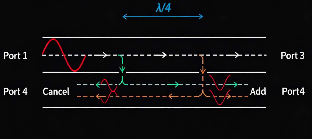
As shown in the figure, the coupling structure consists of two waveguides separated by a common wall containing two coupling holes. Most of the signal entering Port 1 travels directly to Port 2. While a small portion is coupled into the secondary waveguide through the two holes. Each hole generates both a forward-traveling wave and a backward-traveling wave in the secondary waveguide.
The signal at Port 4 is formed by the combination of two wave components, one from each hole. Because the component from the right hole travels a longer distance, a phase difference exists between the two signals. By properly adjusting the spacing between the holes, the two signals can achieve a 180° phase difference at a specific frequency, causing complete cancellation.
When the hole spacing is λ/4, where λ is the wavelength of the incident signal, the output power at Port 4 becomes zero. For this reason, Port 4 is known as the isolation port.
The signal at Port 3 is also composed of two wave components. Unlike Port 4. These components travel equal distances under ideal conditions and therefore arrive with the same phase.
As a result, the two signals combine constructively and produce an output signal. Port 3 receives a portion of the input power and serves as the coupled output of the device.
Therefore, Port 3 is commonly referred to as the coupling port in directional coupler designs.
It is easy to see that if the wavelength or the spacing between the two apertures is mismatched, the wave cancellation will no longer be perfect. Therefore, the frequency response of the coupler is limited. To increase the usable bandwidth, a multi-aperture structure can be used.
Does a Directional Coupler Need Electrical Power?
A directional coupler is a passive radio frequency device that operates solely on the energy of the input signal, requiring no external power supply.
It separates forward and reverse signals in a transmission line using the principle of electromagnetic coupling, enabling functions such as signal monitoring and power distribution.
What are the Losses in Directional Coupler?
The losses in a directional coupler mainly include insertion loss and coupling loss. The specific values of which vary depending on factors such as coupling degree, operating frequency, and structural design.
1. Insertion Loss
Insertion loss refers to the energy loss when a signal is transmitted from the input terminal (port 1) to the through terminal (port 2), usually expressed in decibels (dB).
In practical applications, insertion loss is generally between 0.1dB and 5dB, depending on the coupling degree and device design. For example, a directional coupler with a coupling degree of 30dB may have an insertion loss of around 0.1dB. And a directional coupler with a lower coupling degree (such as 6dB) may have an insertion loss of around 1.2dB.
2. Coupling Loss
Coupling loss refers to the energy loss when a signal is coupled from the main line to the secondary line (coupling port), and is closely related to the coupling degree. The higher the coupling degree, the lower the coupling loss. The coupling losses corresponding to common coupling degrees are as follows:
- Coupling degree 3dB: Coupling loss approximately 3dB;
- Coupling degree 6dB: Coupling loss approximately 1.26dB;
- Coupling degree 10dB: Coupling loss approximately 0.46dB;
- Coupling degree 20dB: Coupling loss approximately 0.04dB;
- Coupling degree 30dB: Coupling loss approximately 0.004dB.
3. Factors Affecting Loss
- Coupling Degree: Higher coupling degree results in lower coupling loss, but insertion loss may increase.
- Operating Frequency: At high frequencies, loss may increase due to dielectric loss, radiation, etc.
- Structural Design: Different structures such as microstrip lines, waveguides, and coaxial lines have different loss characteristics. For example, microstrip line directional couplers may have higher dielectric loss at high frequencies. And waveguide directional couplers are more suitable and have lower loss at low frequencies.
- Manufacturing Process: Process parameters such as linewidth, spacing, and dielectric material affect loss.
Example: If using a directional coupler with a coupling of 20dB, its insertion loss may be between 0.1dB and 1.5dB (depending on the design and frequency). The coupling loss is approximately 0.04dB. In practical applications, accurate values must be obtained from the specific model and parameter manual.
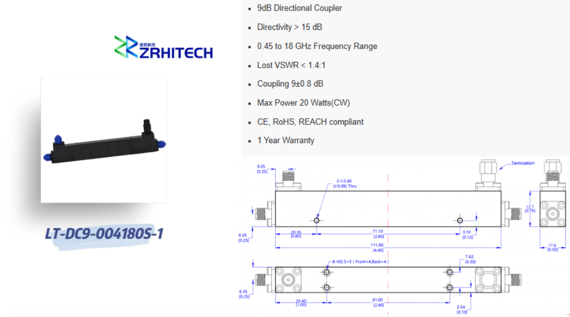
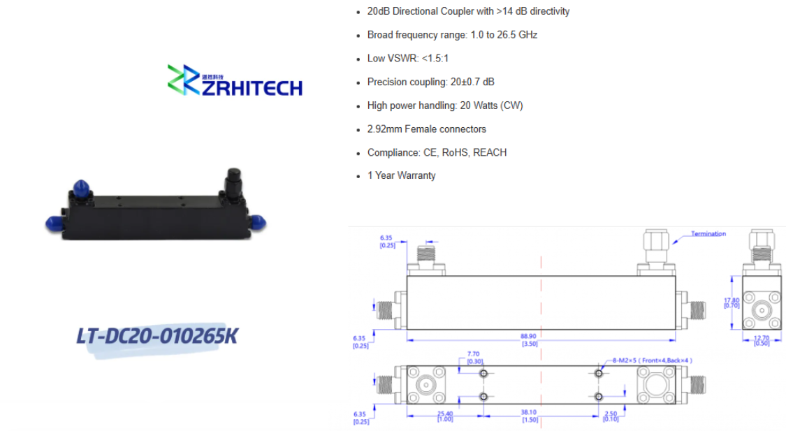
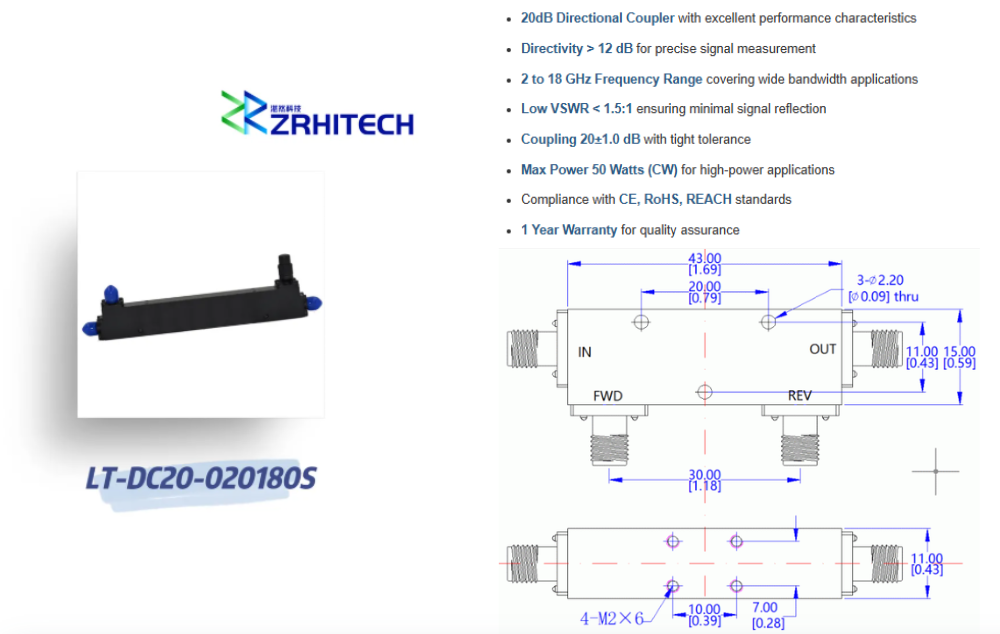
ZR Hi-Tech’s Product Advantages and Core Capabilities
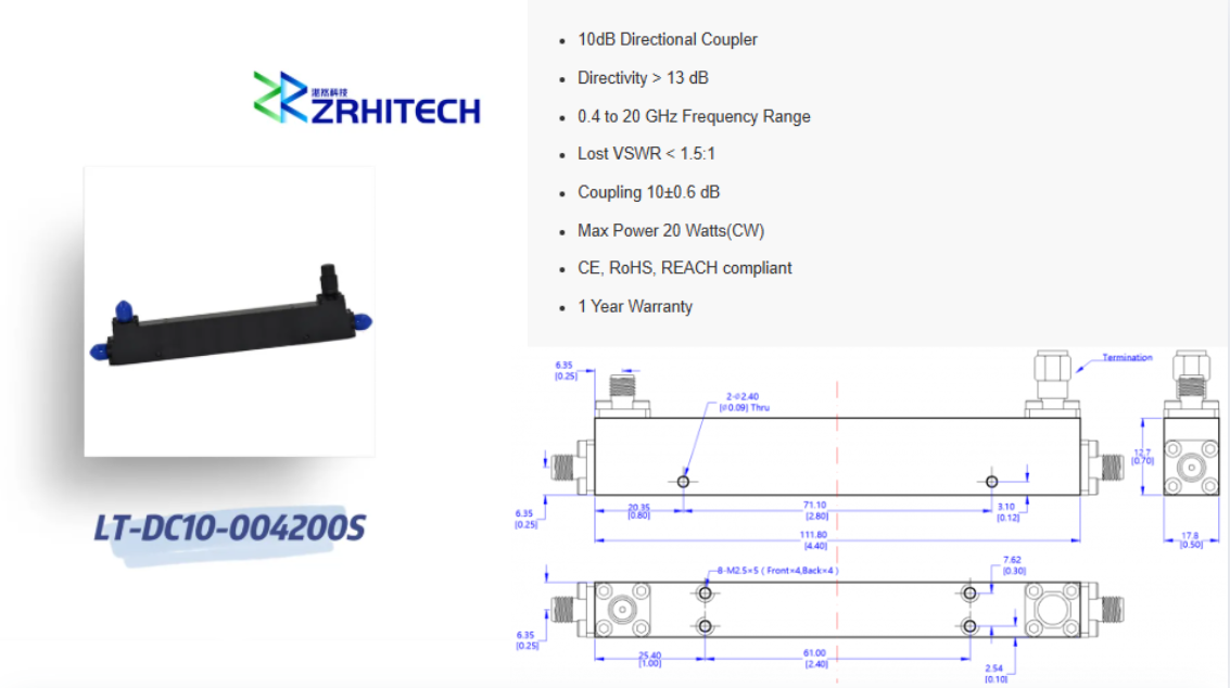
With deep technological expertise, we have built a comprehensive product portfolio of directional couplers, dedicated to providing professional solutions for our customers.
High Reliability Assurance: Our directional coupler product line adheres to stringent quality standards, undergoes comprehensive environmental stress screening and reliability testing. And complies with CE, RoHS, and REACH standards.
Deep Customization Services: We possess strong custom development capabilities and can provide flexible customization services based on specific customer needs. For customized specifications or special requirements, please contact us directly.
If you are looking for a reliable directional coupler manufacturer solution for your project, please consult with ZR Hi-Tech experts!