Newsroom
RF Power Divider and Combiner: Not As Simple As You Think
In RF circuit design, we often need to split RF signals, that is, to divide a single signal into multiple signals, such as in antenna diversity design. It is also common to combine multiple signals into one, that is, to synthesize multiple signals into a single signal, such as in antenna multiplexing. In RF design, the device used to split signals is called a power divider, while conversely, the device used to combine signals is called a combiner.

So in most cases, a power divider can also be used as a combiner, but in some special cases, not all power dividers can be used as combiners.
Main Specifications of Power Divider and Combiner
First of all, as a radio frequency device, it needs to meet its operating conditions in order to perform well in the circuit. The main specifications of an RF power splitter include:
Frequency range:
The operating frequency range of a power divider is the foundation of this power divider. In fact, every RF device has its own operating frequency. From a small RF resistor to an entire RF system, frequency is the most fundamental parameter.
Parameters involving the frequency range, including the operating bandwidth BW, center frequency f0, start and stop frequencies f1 & f2, etc.
The units of frequency are Hz, kHz, MHz, GHz, THz, etc.
Distribution Loss:
The allocation loss of a power divider refers to the ratio between the output signal and the input signal after the signal passes through the power divider, usually expressed in dB.
10log(1/N) dBInsertion loss:
After the signal passes through the power splitter, the actual output signal minus the value reduced by the division loss is the insertion loss. This is usually caused by the transmission line loss of the power splitter itself, matching loss, and so on.
Return Loss:
Return loss is also a very important indicator, used to represent the matching condition of each port of the power splitter. The smaller the return loss, the better the matching. Return loss is also often replaced by the voltage standing wave ratio (VSWR).
Isolation:
The isolation between the two branch ports of a power divider is also an important indicator to ensure that signals between the ports do not interfere with each other.
Power capacity:
For any RF device, power capacity is an indicator that cannot be ignored, especially in high-power situations. It is essential to pay attention to the power capacity of the power divider.
Of course, the main indicators of a combiner, besides insertion loss, are the same as those of a power splitter. Insertion loss can be understood as combiner gain. For example, if two signals of equal power pass through a 3dB power splitter, the combined signal power is twice that of a single signal, which means the power increases by 3dB.
Types of Power Divider
Based on whether power is needed, power dividers can be divided into active power dividers and passive power dividers, but most power dividers are passive devices.
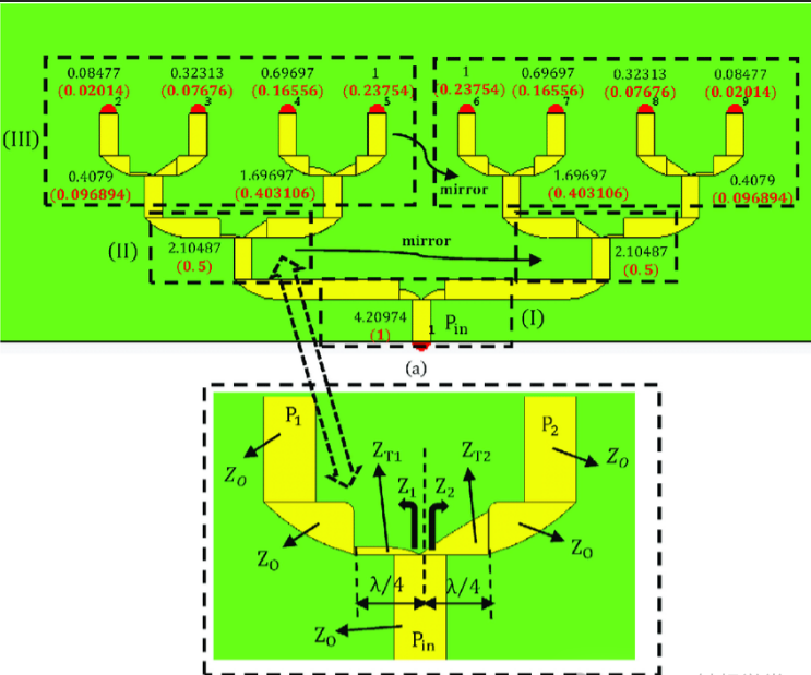
From the perspective of the topology of power dividers, there are also star-type power dividers, Wilkinson power dividers, Gysel power dividers, and so on.
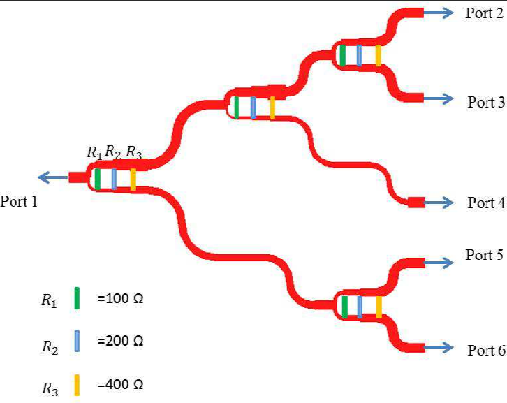
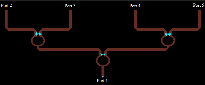
Of course, these power dividers can all be made as equal or unequal power dividers, and can also be made as one-to-two, one-to-three, one-to-four, or even more power dividers.
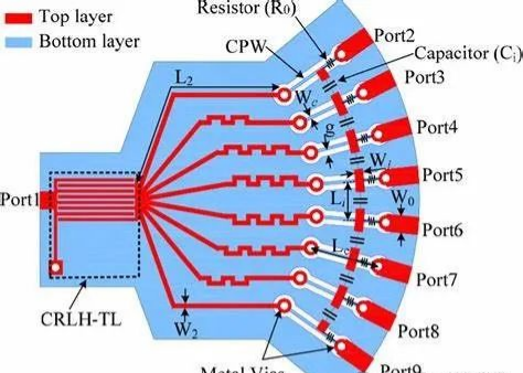
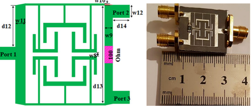
Diagram of The Power Divider
This section compiles some illustrations of power dividers, so everyone can first get familiar with the structural features of this RF device.