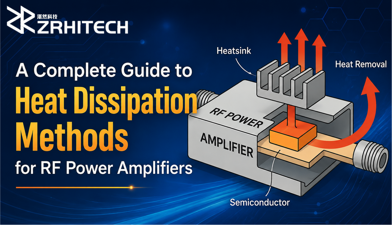
Newsroom
About Low Noise Amplifier | Principles, Applications and more…
With the development of wireless communication, the industry is paying more and more attention to the performance of RF front-end solutions.
As the first-stage active module of the receiver, the LNA (Low Noise Amplifier) has a very important impact on the performance of the receiver system.
What is a Low Noise Amplifier?
A low-noise amplifier (LNA) is an amplifier with a very low noise figure. Its function is to amplify the weak radio frequency signals received by the antenna while minimizing the introduction of noise.
An LNA can effectively improve the receiver’s receiving sensitivity, thereby increasing the transmission distance of the transceiver. Therefore, the quality of the LNA design directly affects the communication quality of the entire communication system.
Why Use a Low Noise Amplifier?
A low-noise amplifier (LNA) is a crucial component of an RF receiver. Its primary function is to amplify the weak signal received from the air by the antenna, improving receiver sensitivity and dynamic range, reducing interference, and providing usable data for demodulation.
Specifically, an LNA enhances receiver sensitivity and dynamic range. In receiver circuitry, the signal itself is attenuated to some extent due to various components (such as mixers and filters). If the signal strength is too weak, it may be masked by noise in the receiver circuitry, preventing effective reception and processing.
The role of an LNA is to amplify the signal to a sufficient strength for processing by subsequent receiver circuitry while minimizing the impact on the receiver’s noise figure. Modern wireless communication tools demand increasingly higher requirements, including low power radiation, long operating distances, and wide coverage, which places higher demands on system receiver sensitivity.
0.02 to 1 GHz 0dBm Low Noise Amplifier with 25 dB Small Signal Gain
How to Select a Low Noise Amplifier?
When evaluating amplifier noise performance for low-noise designs, all potential noise sources should be considered.
The primary noise contribution of an operational amplifier depends on the source resistance, specifically:
- Rs >> Rs, op: Current noise referred to the input dominates;
- Rs = Rs, op: Amplifier noise is negligible; resistive noise dominates;
- Rs << Rs, op: Voltage noise referred to the input dominates.
In summary, interference signals can be reduced or eliminated by:
- Good wiring techniques to reduce parasitic effects
- Good grounding techniques, such as isolation between digital and analog grounds
- Good shielding
For resistive noise sources, follow these rules:
- Limit the bandwidth according to application requirements
- Minimize resistance values as much as possible
- Use low-noise resistors, such as those using large metal sheet, wire-wound, and thin-film metal technology
- Minimize the number of resistive noise sources.
How to Use a LNA?
The following section explains how to use a low-noise amplifier (LNA) by discussing its working principle, characteristics, performance indicators, design considerations, and applications in wireless communication systems:
The Working Principle of a Low Noise Amplifier
The working principle of a Low Noise Amplifier (LNA) mainly includes:
1. Input Matching and Signal Reception
The input RF signal first passes through an input matching network. This network effectively transmits the weak signal received by the antenna to the LNA’s input, ensuring maximum signal transmission efficiency while suppressing unwanted frequency components and noise.
2. Signal Amplification
The signal entering the LNA is then amplified. This amplification process is typically performed by transistors or integrated circuits within the amplifier. The amplifier design needs to consider maximizing the signal amplification factor (gain) while minimizing internally generated noise.
3. Noise Suppression
Unlike other types of amplifiers, LNAs place particular emphasis on suppressing noise while amplifying the signal. This is usually achieved through careful material selection and optimized circuit layout, such as using low-noise transistors, optimizing bias circuitry to reduce static noise, and employing noise filtering techniques.
4. Output Matching and Signal Output
The amplified and noise-suppressed signal then passes through an output matching network. This network effectively transmits the amplified signal to subsequent circuits and ensures that the output signal’s power and spectral characteristics meet system requirements.
10dBm Low Noise Amplifier with 35 dB Small Signal Gain Perfect for 18 to 26.5 GHz
The Features of Low Noise Amplifiers
The most prominent feature of an LNA is its low noise. Through optimized design and the use of high-performance electronic components, the noise generated by the amplifier itself is controlled to an extremely low level, ensuring that the quality of the input signal is not excessively compromised.
1. High Gain
It can significantly amplify weak signals, increasing signal strength for subsequent processing.
2. Good Linearity
It ensures that excessive nonlinear distortion is not introduced during signal amplification, thus accurately preserving the original characteristics of the signal.
The Performance Metrics of the Low Noise Amplifier
Noise Figure (NF)
A key metric measuring the internal noise level of a circuit or system, representing the ratio of the signal-to-noise ratio (SNR) at the amplifier’s input to its output. A lower noise figure indicates better amplifier noise performance.
Gain (G)
The amplification capability of an LNA, measured in dB. Linearity: Includes parameters such as P1dB and OIP3, used to measure the degree of nonlinear distortion produced by the amplifier when processing strong signals.
Stability
Ensuring stable operation of the LNA under various operating conditions, avoiding problems such as self-oscillation and oscillation.
Gain
While maintaining a low cascaded noise figure, a lower gain is better to avoid affecting the dynamic range and interference immunity of the received signal.
Linearity
Maintaining linearity across the entire receiving dynamic range is crucial, especially when processing strong signals, to ensure accurate demodulation and decoding.
Noise Figure Optimization
By selecting appropriate components and optimizing circuit layout, the noise figure can be minimized to improve receiver sensitivity.
Application of Low Noise Amplifier in Wireless Communication Systems
In wireless communication systems, low-frequency amplifiers (LNAs) are commonly used to amplify weak radio signals, such as in mobile phones, Wi-Fi routers, and base stations. They increase the strength of the received signal, thereby improving communication quality and coverage.
In radio frequency transceivers, LNAs are widely used at the antenna end to amplify the received weak signal for subsequent processing and demodulation. By optimizing design and selecting appropriate components, LNAs can achieve optimal performance in various application scenarios, thereby improving system reliability, sensitivity, and performance.
LNAs are widely used in wireless communication, radar, satellite communication, electronic warfare, medical equipment, and other fields, and are an indispensable and important component in modern electronic systems.
5.8 to 40 GHz 10dBm Low Noise Microwave Amplifier With 30 DB Small Signal Gain
How to Power an LNA?
Powering a low-noise amplifier (LNA) requires comprehensive consideration of power supply stability, noise suppression, and circuit design. Here are the key points and methods:
1. Choosing the Appropriate Power Supply Type
Linear Regulator (LDO): High Power Supply Rejection Ratio (PSRR) LDOs are recommended, such as TI’s TPS718xx and TPS719xx series. These effectively filter power supply noise and reduce its impact on LNA performance. The higher the PSRR of the LDO, the better it suppresses input power supply noise and ripple, ensuring output voltage stability.
Battery Power: For portable applications or applications with extremely high power supply noise requirements, two 9V batteries can be connected in series, with power on/off controlled by a DPDT switch. Battery power offers the advantage of low noise, but battery life and replacement frequency must be considered.
2. Optimizing Power Supply Circuit Design
Filtering and Decoupling: Add filter capacitors (such as 0.1μF or 10μF ceramic capacitors) to the power input and output terminals, placing them close to the power supply pins of the LNA chip to suppress high-frequency noise. Simultaneously, use ferrite beads (such as Y1, Y2, Y3) to filter the power lines, further reducing noise.
Power Line Routing: Follow the “capacitor first” principle, ensuring current flows through the filter capacitor before entering the LNA chip. Power lines should be as short and wide as possible to reduce parasitic inductance and resistance, thus reducing power supply noise propagation.
3. Controlling Power Supply Noise
Avoiding Power Supply Ripple: If using a switching power supply (DC-DC converter), select a model with fast transient response and low output ripple, and further optimize it using external filtering circuitry. For LNAs, power supply ripple should be controlled within millivolts to avoid interference with signal amplification.
Isolating Power Supply Interference: Separate the LNA’s power supply from other circuits (such as digital circuits) to avoid mutual interference. If complete isolation is not possible, use ferrite beads or common-mode inductors for isolation.
4. Considering Power Supply Voltage and Current Requirements
Voltage Matching: Select an appropriate power supply voltage according to the LNA chip’s datasheet. For example, some LNA chips operate at 3.3V, 5V, or 12V. It’s crucial to ensure the power supply output voltage remains stable within the chip’s required range.
Current Margin: A certain current margin should be provided to meet the current demands of the LNA under different operating conditions. For instance, if the typical operating current of an LNA is tens of milliamps, the power supply output current should be at least twice that to ensure the power supply does not experience voltage drops due to overload.
5. Analog Switch Controlled Power Supply
If dynamic control of the LNA’s power supply is required, it is recommended to use an analog switch (such as ADG1401) to switch the power supply on and off, rather than directly controlling the LDO’s enable pin. Analog switches have a fast response time, reducing transient noise during power switching and preventing it from affecting LNA performance.
Note: In practical applications, specific design and optimization are required based on the specific LNA chip specifications and system requirements.
1-18 GHz 0dBm Low Noise Amplifier with 39 dB Small Signal Gain for Optimal Signal Amplification
How Do You Test an LNA?
Testing low-noise amplifiers (LNAs) primarily involves measuring key parameters such as noise figure, gain, and linearity. Below are common testing methods and precautions:
Noise Figure Testing
1. Y-Factor Method
Use a calibrated noise source, noise switch, spectrum analyzer, or noise figure analyzer.
Measure the noise power at the LNA output in both cold (room temperature) and hot (reverse bias generates additional noise) states. Calculate the Y-factor (the ratio of hot to cold noise power) to obtain the noise figure.
Note: This assumes a 50-ohm noise source match. Traditional methods are sensitive to input mismatch and may introduce errors.
2. Cold Source Method
Measure the noise power at the LNA input using a vector network analyzer (VNA) with cold termination. The VNA automatically subtracts the amplified input noise, retaining only the LNA’s own noise, and calculates the noise figure.
This method allows for full vector correction, resulting in higher accuracy, and is particularly suitable for high-precision testing.
Gain Testing
1. Small Signal Gain
Use a VNA to measure the S21 parameter, directly reflecting the LNA’s positive gain.
If the LNA gain is high or the power is large, a signal generator can be used to drive the input terminal, and a power meter or spectrum analyzer can be used to measure the output power to calculate the gain.
2. Large Signal Gain
By changing the input power, observe the change in output power, plot the gain curve, and determine the 1dB compression point (P1dB), which is the input power at which the gain decreases by 1dB.
Linearity Testing
1. 1dB Compression Point (P1dB)
Gradually increase the input power and measure the output power. When the output power differs from the linear gain by 1dB, the corresponding input power is P1dB, reflecting the upper limit of the LNA’s linear operating range.
2. Third-Order Intermodulation Intercept (OIP3)
Input two signals of equal amplitude but different frequencies, and measure the power of the third-order intermodulation product. The input or output power at which it equals the fundamental power is OIP3, measuring the degree of nonlinear distortion of the LNA.
Other Parameter Tests
1. S-parameter Test
Use a VNA to measure parameters such as S11 (input reflection coefficient), S22 (output reflection coefficient), and S12 (reverse transmission coefficient) to evaluate the LNA’s input-output matching and isolation performance.
2. Phase Noise Test
For ultra-low phase noise LNAs, a phase noise testing system is required. Using equipment such as a mixer and spectrum analyzer, the phase noise level at a specific frequency is measured.
Testing Precautions
1. Instrument Calibration
Before testing, the VNA, noise source, spectrum analyzer, and other instruments must be calibrated to ensure measurement accuracy.
2. Environmental Control
Tests should be conducted in an environment with stable temperature and free from electromagnetic interference to avoid environmental factors affecting the measurement results.
3. Input-Output Matching
Ensure that the LNA’s input and output ports are matched with the test instruments (e.g., 50 ohms) to reduce reflection and distortion.
0.01 to 1 GHz 0dBm Low Noise Amplifier with 25 dB Small Signal Gain
What is a Good Noise Figure for LNA?
The noise figure is a key metric for measuring the internal noise level of a circuit or system. It represents the ratio of the signal-to-noise ratio (SNR) at the amplifier’s input to the SNR at its output. A lower noise figure indicates better amplifier noise performance.
An ideal amplifier has a noise figure of 1 (0 dB), while currently used LNAs typically have a noise figure ≤ 1 dB.
About ZR Hi-Tech: Leading Low Noise Amplifier Manufacturer
ZR Hi-Tech is a company specializing in integrated circuit manufacturing, committed to providing customers with high-performance, high-reliability integrated circuit solutions. Our team consists of experienced professionals.
If you are looking for a reliable low noise amplifiers manufacturer solution for your project, please consult with ZR Hi-Tech experts!
thousand grade and ten thousand grade Purification workshops
ZR Hi-Tech’s Product Advantages and Core Capabilities
With deep technological expertise, we have built a comprehensive product portfolio of low noise amplifiers, dedicated to providing professional solutions for our customers.
High Reliability Assurance: Our low noise amplifier product line adheres to stringent quality standards, undergoes comprehensive environmental stress screening and reliability testing, and complies with CE, RoHS, and REACH standards.
Deep Customization Services: We possess strong custom development capabilities and can provide flexible customization services based on specific customer needs. For customized specifications or special requirements, please contact us directly.