Newsroom
RF Power Amplifier IC: A Guide to Performance, Applications, and Selection Criteria
In the rapidly evolving world of radio frequency (RF) technology, the RF power amplifier IC stands as a cornerstone component for boosting signal strength in wireless systems. Whether you’re designing for telecommunications, radar, or consumer electronics, understanding the intricacies of these integrated circuits is essential for making informed purchasing decisions.
This guide delves into the fundamentals, performance metrics, and practical considerations to help buyers navigate the market effectively.
What Is an RF Power Amplifier IC?
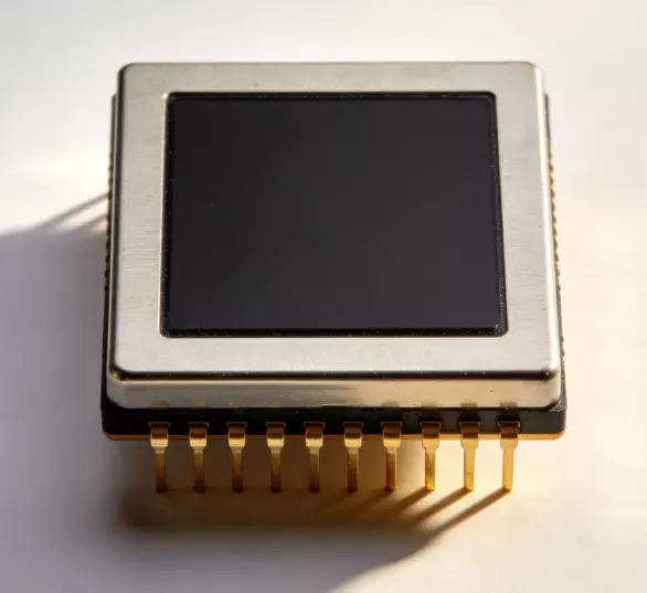
An RF power amplifier IC is an integrated circuit designed to amplify low-power radio frequency signals to higher power levels suitable for transmission. Unlike general-purpose amplifiers, these ICs are optimized for RF applications, handling frequencies typically from a few MHz up to tens of GHz. They convert weak input signals into robust outputs capable of driving antennas or other high-power loads while maintaining signal integrity.
At its core, an RF power amplifier IC consists of RF power amplifier transistors (often based on technologies like GaAs, GaN, or SiC) integrated with matching networks, bias circuits, and sometimes protection features on a single chip. This integration reduces size, cost, and complexity compared to discrete designs. For buyers, the appeal lies in their efficiency in space-constrained applications, such as mobile devices or base stations.
These ICs are crucial in scenarios where signal amplification is needed without introducing excessive distortion or noise. For instance, in a transmitter chain, the RF power amplifier IC acts as the final stage, ensuring the signal reaches its destination with sufficient power. Key benefits include high gain, broad bandwidth, and improved thermal performance, making them ideal for modern wireless standards like 5G.
How Does an RF Power Amplifier IC Work?
The operation of an RF power amplifier IC revolves around transistor amplification principles. When a low-power RF signal enters the IC, it modulates the gate or base of the internal transistors, controlling the flow of current from the power supply. This results in an amplified output signal that mirrors the input but at a much higher power level.
Internally, the IC employs stages such as pre-amplification, power amplification, and output matching. Biasing circuits set the operating point to determine the RF power amplifier class (more on this later), while impedance matching networks ensure maximum power transfer and minimize reflections. Efficiency is achieved by converting DC power from the supply into RF output power, with losses manifesting as heat.
For example, in a GaN-based RF power amplifier IC, the wide bandgap material allows for higher voltage operation and better efficiency at high frequencies. The signal path involves input matching to optimize gain, amplification through the transistor core, and output matching to interface with the load. Buyers should note that proper biasing and supply voltage are critical to avoid saturation or distortion, which could degrade performance in real-world applications.
Key Performance Parameters Buyers Should Know
When evaluating an RF power amplifier IC, several parameters define its suitability for your application. Gain, typically in dB, measures amplification capability—higher values mean stronger output for a given input. Bandwidth indicates the frequency range over which the IC maintains specified performance, crucial for wideband systems.
Output power, often specified as P1dB (1 dB compression point), is the level where gain drops by 1 dB, signaling the onset of nonlinearity. Efficiency, expressed as a percentage, shows how effectively the IC converts DC power to RF output—vital for battery-powered devices. Noise figure quantifies added noise, with lower values preserving signal quality.
Linearity parameters like IP3 (third-order intercept point) assess distortion under multi-tone signals, important for avoiding interference in crowded spectra. Finally, VSWR (voltage standing wave ratio) reflects matching quality, impacting reliability. Buyers should prioritize these based on application needs, such as high efficiency for portable devices or superior linearity for radar.
RF Power Amplifier IC Types and Classes
RF power amplifier ICs come in various types, primarily differentiated by semiconductor material: GaAs for high-frequency linearity, GaN for high power and efficiency, and Si for cost-effective low-power applications. Classes define operation based on conduction angle.
Class A offers maximum linearity (360° conduction) but low efficiency (around 30%), suitable for precision applications. Class B (180° conduction) improves efficiency to 60-70% with push-pull configurations but introduces crossover distortion. Class AB balances the two, with conduction slightly over 180°, providing good linearity (efficiency 50-60%) for wireless comms.
Class C (less than 180°) prioritizes efficiency (up to 80%) over linearity, ideal for tuned RF power amplifier circuits like FM transmitters. Switching classes like class D and E use pulse-width modulation for efficiencies exceeding 90%, perfect for digital signals but requiring filtering to reduce harmonics.
Common Applications of RF Power Amplifier ICs
RF power amplifier ICs are ubiquitous in wireless systems. In telecommunications, they boost signals in base stations and handsets for 5G coverage. Satellite communications rely on them for uplink amplification, ensuring data reaches orbit.
Radar systems use high-power ICs for pulse amplification, enabling long-range detection in defense and aviation. Medical devices like MRI employ them for precise RF excitation. Consumer electronics, such as Wi-Fi routers and Bluetooth modules, integrate low-power variants for reliable connectivity.
Industrial applications include plasma generation and RF heating, where efficiency drives cost savings. Emerging uses in autonomous vehicles leverage them for V2X communication, highlighting their versatility.
How to Choose the Right RF Power Amplifier IC
Selecting an RF power amplifier IC starts with defining requirements: frequency range, output power, and efficiency. Match the IC’s bandwidth to your system’s needs—wideband for multi-protocol devices.
Evaluate linearity for distortion-sensitive apps; high IP3 is key. Consider integration level—some ICs include matching, simplifying design. Thermal specs are crucial; ensure junction temperature stays below limits.
Budget for RF power amplifier testing: Simulate performance with tools like ADS. Compare vendors on reliability data and support. For high-volume buys, prioritize scalability and cost per unit.
Steps to choose:
- Define frequency and power needs.
- Assess efficiency and linearity trade-offs.
- Check thermal and package compatibility.
- Verify with datasheets and simulations.
- Evaluate supplier ecosystem.
RF Power Amplifier IC vs. RF Power Amplifier Module
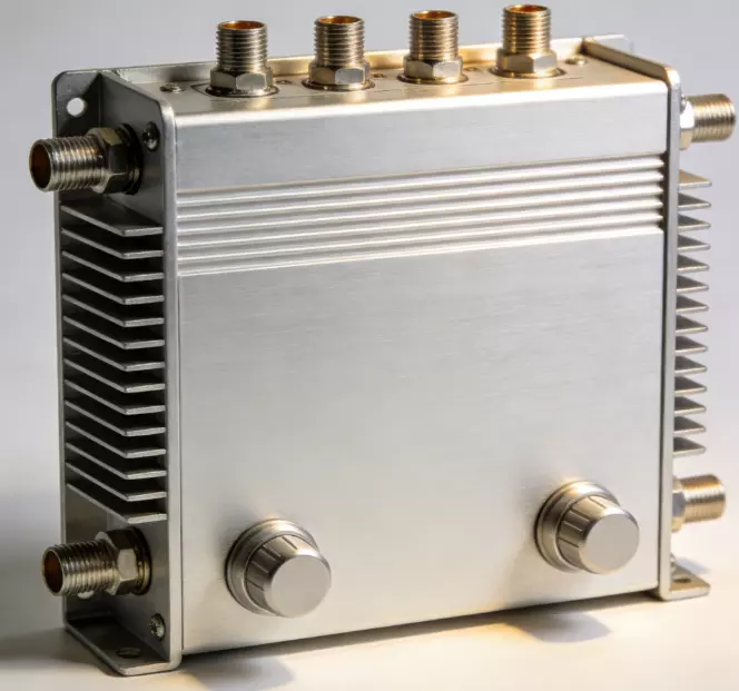
An RF power amplifier IC is a bare chip requiring external components for matching and biasing, offering customization but demanding expertise. RF power amplifier modules integrate the IC with passives, heatsinks, and connectors in a ready-to-use package, easing integration.
ICs excel in compact, cost-sensitive RF power amplifier designs like handsets, while modules suit rapid prototyping or high-power apps like base stations, reducing time-to-market. Modules often include protection, improving reliability, but at higher cost and size.
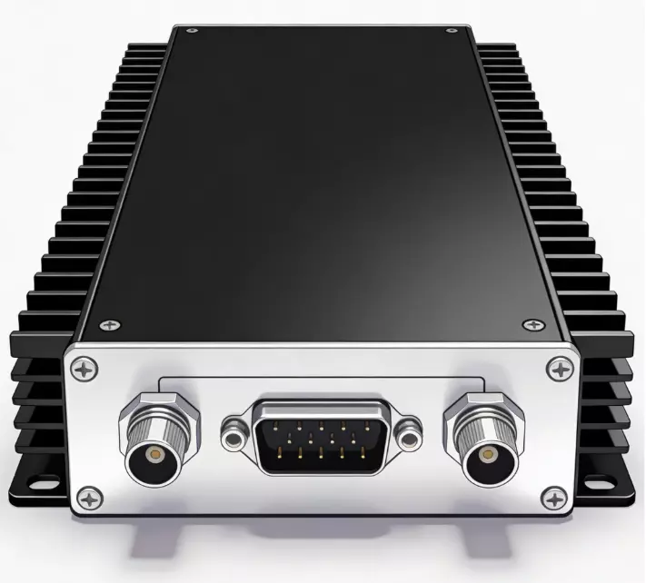
Thermal Management and PCB Design Considerations
RF power amplifier ICs generate significant heat, risking performance degradation or failure. Thermal resistance (θJA) measures heat dissipation; lower values indicate better cooling.
Use heatsinks, thermal vias, and copper pours on PCBs to spread heat. Materials like FR4 suffice for low power, but high-frequency apps benefit from Rogers laminates for low loss.
Design tips: Place ICs away from heat sources, use multi-layer boards for ground planes, and simulate with tools like ANSYS. Active cooling (fans) may be needed for high-power setups.
Typical Specifications to Review Before Purchasing
Before buying, scrutinize: Frequency range (e.g., 0.1-6 GHz), gain (15-25 dB), P1dB (25-35 dBm), efficiency (40-60%), and noise figure (2-4 dB). Check supply voltage (3-28V) and package (QFN, LFCSP). Review IMD3 for linearity, ESD rating for robustness, and MTBF for reliability. Ensure compliance with standards like RoHS.
Future Trends in RF Power Amplifier IC Technology
Advancements in GaN-on-Si promise cost reductions while maintaining high power RF power amplifier. Integration with AI for adaptive biasing will enhance efficiency. Millimeter-wave support for 6G is emerging, with wider bandwidths. Sustainability drives eco-friendly materials, and miniaturization enables denser integrations in IoT.
Conclusion
Navigating the RF power amplifier IC landscape requires balancing performance, cost, and application fit. As a buyer, focusing on RF power amplifier key parameters and trends ensures optimal choices.
For reliable solutions, consider RF power amplifier manufacturers like ZR Hi-Tech, known for innovative RF power amplifier ICs tailored to demanding environments. With the right selection, your systems will achieve superior efficiency and reliability.