Newsroom
RF Power Amplifier Circuit: The Ultimate Guide for Engineers and Enthusiasts
In the world of radio frequency (RF) technology, the RF power amplifier circuit stands as a cornerstone component, enabling efficient signal transmission across vast distances. Whether you’re designing wireless communication systems, radar equipment, or broadcasting setups, understanding the intricacies of an RF power amplifier circuit is essential.
This comprehensive guide delves deep into the fundamentals, design principles, types, applications, and advancements in RF power amplifier circuits, providing you with the knowledge to make informed decisions for your projects.
What is an RF Power Amplifier Circuit?
An RF power amplifier circuit is a specialized electronic circuit designed to increase the power level of radio frequency signals while maintaining signal integrity. Unlike low-power amplifiers used in audio systems, RF power amplifiers handle high-frequency signals, typically ranging from 3 kHz to 300 GHz, and are optimized for applications requiring significant output power, such as telecommunications and satellite systems.
At its core, an RF power amplifier circuit takes a low-power RF input signal and amplifies it to a level suitable for transmission. This amplification is achieved through active devices like transistors (e.g., bipolar junction transistors, field-effect transistors, or gallium nitride-based devices) that operate in a linear or switched mode. The circuit must manage challenges like heat dissipation, impedance matching, and harmonic distortion to ensure efficient operation.
For instance, in a basic RF power amplifier circuit, the input signal is fed into a pre-amplifier stage for initial gain, followed by a power stage where the bulk of amplification occurs. Output matching networks are crucial to transfer maximum power to the load, such as an antenna.
To visualize this, consider a typical schematic:
This diagram illustrates the key elements, including input matching, amplification stages, and output filtering, which are standard in modern RF power amplifier circuits.
Basic Principles of RF Power Amplifier Circuits
Understanding the principles behind RF power amplifier circuits requires grasping concepts like gain, efficiency, linearity, and bandwidth. Gain refers to the ratio of output power to input power, often expressed in decibels (dB). For RF applications, power gain is critical, as it determines how much the signal is boosted.
Efficiency is another key metric, calculated as the ratio of RF output power to DC input power. High efficiency reduces power consumption and heat generation, which is vital for battery-operated devices or high-power systems. Linearity ensures the amplified signal remains faithful to the input, avoiding distortion that could degrade signal quality in modulation schemes like QAM or OFDM.
Bandwidth defines the range of frequencies the amplifier can handle effectively. Wideband RF power amplifiers are essential for multi-band operations in modern wireless standards like 5G and beyond.
The operation of an RF power amplifier circuit relies on biasing the active device appropriately. For example, in a transistor-based circuit, the base or gate bias sets the operating point, influencing the amplifier’s class and performance. Impedance matching, often using transformers, capacitors, and inductors, prevents signal reflections and maximizes power transfer.
Types of RF Power Amplifiers
RF power amplifiers are classified based on their biasing and conduction angle, which affect efficiency, linearity, and distortion. The main classes include A, B, AB, C, D, E, and F, each suited for specific applications.
Class A Amplifiers
Class A amplifiers operate with the transistor conducting for the entire input cycle, providing excellent linearity but low efficiency (typically 25-30%). They are ideal for applications requiring minimal distortion, such as in high-fidelity RF signal amplification.
In an RF power amplifier circuit of Class A, the output waveform closely mirrors the input, as shown here:
This waveform demonstrates the full conduction, making Class A suitable for low-power RF stages but less efficient for high-power needs.
Class B and AB Amplifiers
Class B amplifiers conduct for half the cycle, improving efficiency to around 78% but introducing crossover distortion. Class AB, a hybrid, conducts slightly more than half, balancing linearity and efficiency (50-70%). These are common in push-pull configurations for RF power amplifier circuits in audio and moderate-power RF systems.
Class C Amplifiers
Class C amplifiers conduct for less than half the cycle, achieving high efficiency (up to 90%) but with significant distortion. They are tuned for specific frequencies and used in RF transmitters where harmonics can be filtered out. In RF power amplifier circuits for FM broadcasting, Class C is prevalent due to its power-handling capabilities.
Switched-Mode Amplifiers (Class D, E, F)
These classes use switching techniques for even higher efficiency (90-95%). Class D employs PWM for amplification, Class E uses resonant circuits for zero-voltage switching, and Class F incorporates harmonic tuning. Modern RF power amplifier circuits in 5G base stations often use Class E or F for their superior performance in high-frequency bands.
Key Components in RF Power Amplifier Circuits
Building an effective RF power amplifier circuit involves selecting the right components:
- Active Devices: Transistors like MOSFETs, LDMOS, or GaN HEMTs are the heart. GaN offers high power density and efficiency for high-frequency operations.
- Matching Networks: Input and output networks use lumped elements (capacitors, inductors) or transmission lines to match impedances, typically 50 ohms in RF systems.
- Biasing Circuits: Provide stable DC bias to set the operating class, often including temperature compensation.
- Cooling Systems: Heat sinks or fans manage thermal dissipation, crucial for high-power circuits.
- Protection Circuits: Include over-voltage, over-current, and thermal shutdown to safeguard the amplifier.
Design Considerations for RF Power Amplifier Circuits
Designing an RF power amplifier circuit demands attention to several factors:
- Power Requirements: Determine the required output power (e.g., 10W for handheld devices vs. 1kW for base stations).
- Frequency Range: High frequencies require careful layout to minimize parasitic effects.
- Efficiency vs. Linearity Trade-off: For data-intensive applications, prioritize linearity; for constant-envelope signals, focus on efficiency.
- Thermal Management: Simulate heat flow to prevent junction temperatures from exceeding limits.
- Harmonic Suppression: Use filters to attenuate unwanted harmonics.
- Stability: Ensure the circuit doesn’t oscillate using techniques like negative feedback.
Applications of RF Power Amplifier Circuits
RF power amplifier circuits find applications across industries:
Telecommunications
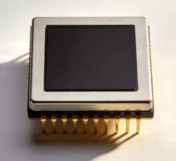
In mobile base stations, they amplify signals for 4G/5G networks, enabling high-speed data transfer. A typical setup includes:
This image shows an LDMOS-based amplifier in a base station, highlighting its role in coverage expansion.
Radar and Defense
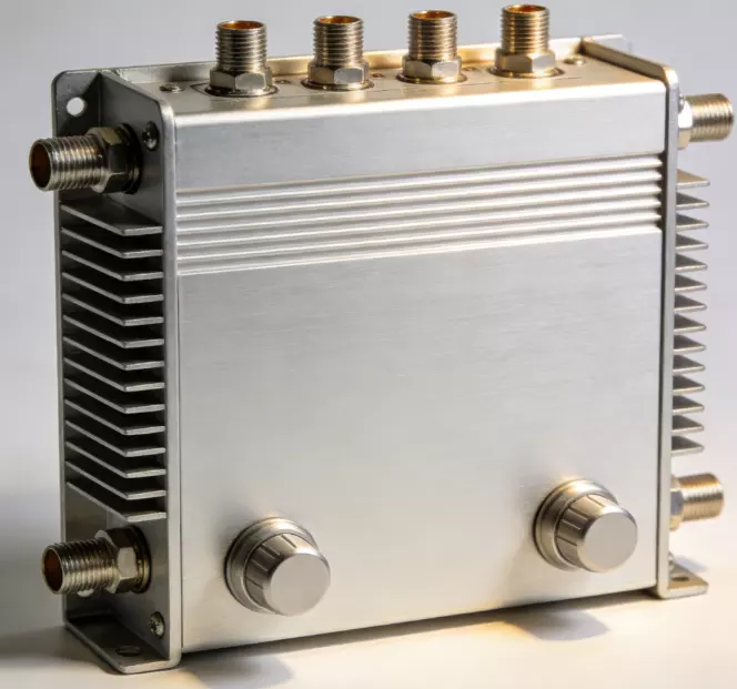
Radar systems use high-power RF amplifiers for long-range detection. Pulse-modulated circuits provide the necessary burst power.
Depicted here is a GaN amplifier for sweep radar, essential in aerospace.
Broadcasting and Satellite Communications
For TV/radio broadcasting, Class C amplifiers ensure strong signals. Satellites rely on traveling wave tube amplifiers (TWTAs) or solid-state power amplifiers (SSPAs) for uplink/downlink.
Medical and Industrial
In MRI machines, RF amplifiers generate magnetic fields. Industrial heating uses them for induction processes.
Advances in RF Power Amplifier Technology
Recent advancements include the shift to GaN and GaAs technologies for higher efficiency and smaller footprints. Doherty architectures combine multiple amplifiers for better efficiency across power levels. Digital predistortion (DPD) corrects nonlinearity in real-time.
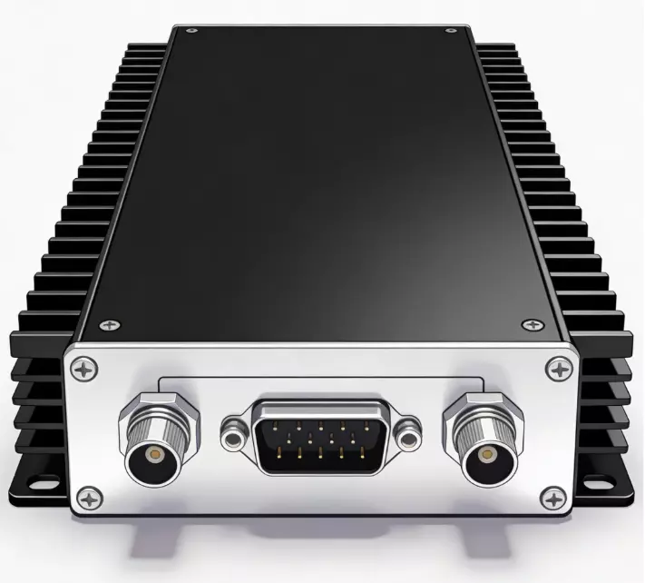
A modern module looks like this:
This compact design exemplifies the integration in contemporary RF power amplifier circuits.
Why Choose ZR Hi–Tech RF Power Amplifiers?
As a premier RF power amplifier manufacturer, ZR Hi–Tech offers a range of RF power amplifier circuits designed for reliability and performance. Our products feature:
- High efficiency ratings.
- Customizable frequency bands.
- Robust protection features.
- Compliance with international standards like FCC and ETSI.
Whether for prototyping or large-scale deployment, ZR Hi–Tech provides solutions that integrate seamlessly into your RF systems.
Conclusion
The RF power amplifier circuit is pivotal in modern electronics, driving innovations in communication and beyond. By understanding its principles, types, and applications, you can harness its potential effectively. At ZR Hi–Tech, we’re committed to delivering top-tier amplifiers that meet your needs. For more information, contact us today.