Newsroom
FM RF Power Amplifier: Design Principles, Working Theory, and Practical Applications
In the world of radio frequency (RF) engineering, the FM RF power amplifier stands as a cornerstone technology for reliable signal transmission. Whether powering local community radio stations or large-scale broadcast networks, these specialized amplifiers take low-level frequency-modulated signals and boost them to the high-power outputs required for effective over-the-air propagation.
FM signals maintain a constant envelope, unlike amplitude-modulated waveforms, which allows designers to prioritize efficiency over strict linearity. This article explores the FM RF power amplifier in depth—from fundamental definitions and operating principles to real-world design considerations, performance metrics, and selection criteria.
What Is an FM RF Power Amplifier?
An FM RF power amplifier is a specialized electronic RF power amplifier circuit that increases the power level of a frequency-modulated (FM) radio-frequency signal while preserving its essential characteristics. In an FM transmitter chain, the modulator produces a low-power carrier (typically milliwatts) whose frequency varies according to the audio input. The FM RF power amplifier serves as the final stage before the antenna, elevating this signal to tens, hundreds, or thousands of watts.
Unlike general-purpose RF amplifiers, FM-specific designs exploit the constant-envelope nature of FM modulation. Amplitude variations are minimal, so the amplifier can operate in nonlinear modes without introducing significant distortion to the recovered audio at the receiver. This enables higher efficiency and simpler cooling compared to linear amplifiers required for AM or complex digital modulations.
Modern FM RF power amplifiers are almost exclusively solid-state, replacing older vacuum-tube designs. They deliver clean, stable output across the standard FM broadcast band while incorporating protection features such as VSWR monitoring, thermal shutdown, and over-current safeguards. In essence, the FM RF power amplifier bridges the gap between low-power signal generation and high-power electromagnetic radiation.
How Does an FM RF Power Amplifier Work?
The operating principle of an FM RF power amplifier revolves around controlled energy transfer from a DC power supply to the RF output. A low-power FM input signal drives the gate or base of one or more active devices—typically LDMOS RF power amplifier or GaN RF power amplifier transistors—causing them to conduct in precise synchronization with the carrier frequency.
In most practical FM RF power amplifier designs, the RF power amplifier transistor is biased into deep Class C operation. The device remains cut off for more than half the RF cycle and conducts only during brief peaks of the input waveform. This pulsed current flows into a high-Q resonant tank circuit (parallel LC network) tuned to the operating frequency. The flywheel effect of the tank reconstructs the sinusoidal output waveform while suppressing harmonics.
Input and output matching networks—often implemented with microstrip lines, lumped inductors, and capacitors—ensure maximum power transfer and stability. Directional couplers sample forward and reflected power for monitoring. The constant-envelope FM signal experiences negligible amplitude distortion even in nonlinear operation, so the frequency deviations carrying the audio information pass through intact.
Power supply decoupling and careful layout minimize parasitic oscillations. Advanced designs incorporate feedback or predistortion if slight linearity improvements are needed, though pure FM applications rarely require them.
What Frequency Range Do FM RF Power Amplifiers Operate In?
Standard FM broadcasting worldwide occupies the VHF band from 87.5 MHz to 108 MHz. Consequently, the vast majority of FM RF power amplifiers are optimized for this 20.5 MHz span, with center-frequency tuning around 98 MHz. Some RF power amplifier designs offer slightly broader coverage (e.g., 76–108 MHz) to accommodate international variations or extended-band community stations.
Narrowband tuning allows designers to achieve exceptionally high efficiency and power gain within the target range. The relatively low frequency (compared to UHF or microwave) permits the use of cost-effective LDMOS transistors and straightforward lumped-element or transmission-line matching networks. Harmonic suppression is straightforward because the second harmonic (175–216 MHz) falls outside most broadcast allocations and can be attenuated with simple low-pass filters.
While some specialized FM RF power amplifiers appear in VHF land-mobile radio (136–174 MHz) or amateur FM repeaters, the 87.5–108 MHz segment dominates commercial broadcast applications. Broadband designs covering multiple octaves exist but sacrifice peak efficiency and are less common for pure FM service.
What Are the Main Classes of FM RF Power Amplifiers?
RF power amplifiers are classified according to the conduction angle of the active device:
- Class A: 360° conduction—highly linear but only ~50% theoretical efficiency. Rarely used in high-power FM due to excessive heat.
- Class AB: 180°–360° conduction—good linearity with 60–70% efficiency. Sometimes employed in driver stages.
- Class B: 180° conduction—up to 78.5% efficiency. Offers a compromise but still generates more heat than necessary for constant-envelope FM.
- Class C: <180° conduction (typically 90°–120°)—the workhorse for FM RF power amplifiers. Efficiency routinely reaches 70–85% in practice and can approach 90% with careful tuning. The tuned output circuit restores the sine wave, making the distortion irrelevant for FM.
Emerging switched-mode classes (D, E, F) push efficiencies above 90% by operating transistors as near-ideal switches, but they require more sophisticated output networks and are gaining traction primarily in compact or energy-conscious designs.
What Power Levels Are Available in FM RF Power Amplifiers?
FM RF power amplifiers span an enormous range to suit every application:
- Low-power exciters and drivers: 1–50 W
- Pallet amplifiers for modular transmitters: 100–1,500 W
- Medium-power standalone units: 500 W–5 kW
- High-power broadcast finals: 5 kW–50 kW+ (often combined in parallel or using tube hybrids for very high power RF amplifier)
A typical 1 kW FM RF power amplifier might require only 5–10 W drive, delivering 20–23 dB gain. Scalability is achieved by paralleling multiple pallets or using hybrid combiners. Modern solid-state RF power amplifier designs achieve these levels with excellent reliability and graceful degradation—if one RF power amplifier module fails, the transmitter continues at reduced power.
What Components Are Used in Modern FM RF Power Amplifiers?
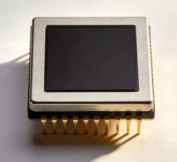
Core active devices include 50 V LDMOS transistors (e.g., BLF188XR, MRF1K50H) or gallium-nitride (GaN) HEMTs for newer high-efficiency designs. These devices feature high power density, excellent thermal characteristics, and ruggedness against high VSWR.
Passive elements include:
- High-Q ceramic capacitors and air-core or toroidal inductors for matching
- Microstrip transmission lines on low-loss PTFE or Rogers substrates
- Ferrite baluns or 90° hybrids for power combining
- Directional couplers (stripline or transformer-based) for power monitoring
- Aluminum or copper heat spreaders with machined fins or liquid cooling for multi-kilowatt units
- Protection circuitry: PIN diodes, relays, temperature sensors, and microcontroller-based fault logic
Modern layouts emphasize short, symmetrical paths to minimize stray inductance and ensure even current sharing in paralleled devices.
How to Design an FM RF Power Amplifier?
Successful FM RF power amplifier design follows a systematic process:
- Define specifications — target output power, frequency band, supply voltage, required gain, efficiency goal, and environmental constraints.
- Select the transistor — using load-line analysis and manufacturer datasheets to verify power capability, gain, and thermal resistance at the operating frequency.
- Determine bias — set gate voltage for desired Class C conduction angle (typically –2 V to –4 V for LDMOS).
- Design matching networks — use Smith-chart techniques or simulation software (Keysight ADS, AWR Microwave Office) to present optimal source and load impedances. Input match for maximum gain and stability; output match for maximum power.
- Implement harmonic filtering — add a low-pass or band-pass output network to meet spectral emission masks.
- Address thermal management — calculate dissipation (P_diss = P_DC – P_out), select heatsink with appropriate thermal resistance, and ensure airflow or liquid cooling.
- Incorporate protection and monitoring — add VSWR, temperature, and current sensing with automatic foldback.
- Prototype, simulate, and iterate — measure gain, efficiency, stability (K-factor or mu), and spurious emissions on the bench. Fine-tune matching elements as needed.
Stability is critical; unconditional stability (K > 1 across all frequencies) prevents oscillations under varying load conditions.
How Efficient Is an FM RF Power Amplifier?
Efficiency remains one of the most compelling advantages of FM RF power amplifiers. A well-designed Class C stage routinely achieves 75–85% DC-to-RF efficiency at rated output. For a 1 kW amplifier drawing 1.3 kW from the supply, only 300 W becomes heat—manageable with moderate cooling.
Real-world factors affecting efficiency include:
- Drive level (slight overdrive improves efficiency but may increase harmonics)
- Supply voltage regulation
- Output matching losses
- Device on-resistance and output capacitance
Switched-mode topologies (Class E or F) can exceed 90% but demand precise timing and higher component Q. Overall system efficiency—including power supply and cooling—typically lands between 65% and 80% for complete transmitter racks. High efficiency translates directly to lower electricity bills and reduced carbon footprint for continuous 24/7 broadcast operation.
What Are Common Problems in FM RF Power Amplifiers?
Even robust designs encounter challenges:
- Thermal issues — hotspots on the transistor die or poor thermal interface materials leading to derating or failure.
- Parasitic oscillations — low-frequency or VHF parasitics caused by unintended feedback paths.
- High VSWR damage — antenna icing, lightning, or connector failure reflecting power back into the amplifier.
- Harmonic radiation — inadequate filtering producing interference in adjacent bands.
- Gain compression and spectral regrowth — although less critical for pure FM, still relevant in hybrid digital-FM (HD Radio) installations.
- Component aging — capacitor drift or solder joint fatigue under thermal cycling.
Mitigation strategies include conservative thermal margins, robust protection circuitry, regular maintenance, and redundant architectures in critical installations.
FM RF Power Amplifier vs. Other RF Amplifiers
FM RF power amplifiers differ markedly from counterparts used in other modulation schemes. Linear amplifiers for AM, SSB, or OFDM must maintain strict linearity across the full dynamic range, forcing operation in Class AB with typical efficiencies of only 30–50% and requiring significant power back-off. In contrast, the constant-envelope FM signal permits deep Class C or switched-mode operation for far higher efficiency and simpler circuitry.
Compared to low-noise amplifiers (LNAs) in receivers, FM RF power amplifiers prioritize power handling and efficiency over noise figure. Broadband amplifiers for test equipment or jamming cover decades of frequency but sacrifice narrowband optimization and peak efficiency. Pulsed radar amplifiers handle extremely high peak powers but operate at low duty cycles, whereas FM units run continuously at high average power.
Applications of FM RF Power Amplifiers
The primary application is commercial FM radio broadcasting—from 100 W community stations to multi-kilowatt urban transmitters feeding tall towers. FM RF power amplifiers also serve:
- VHF two-way radio base stations and repeaters
- Amateur radio FM voice and data links
- Wireless microphone and in-ear monitor systems (where regulatory power limits apply)
- Telemetry and remote control links using FM modulation
- Scientific and industrial RF heating or plasma generation when frequency-modulated control is beneficial
In each case, the amplifier must deliver stable, spectrally clean power while withstanding continuous duty and varying environmental conditions.
How to Choose the Right FM RF Power Amplifier?
Selection involves balancing several factors:
- Power requirement — calculate ERP needed for desired coverage using antenna gain, height, and terrain.
- Frequency agility — fixed-tune vs. broadband or programmable units.
- Efficiency and operating cost — higher efficiency yields lower electricity and cooling expenses.
- Drive power — ensure compatibility with existing exciter output.
- Reliability features — forward/reflected power metering, automatic protection, remote monitoring via SNMP or web interface.
- Physical constraints — rack space, weight, airflow requirements, and environmental rating (IP for outdoor enclosures).
- Regulatory compliance — harmonic suppression, spurious emissions, and safety certifications.
- Budget and support — total cost of ownership including spares and service.
Request load-pull data or efficiency curves from the manufacturer and, whenever possible, request a demonstration unit for bench evaluation under real operating conditions.
Conclusion
The FM RF power amplifier exemplifies elegant engineering: leveraging the unique properties of frequency modulation to achieve outstanding efficiency, reliability, and simplicity in high-power RF transmission. From basic Class C topologies to advanced GaN-based switched-mode designs, these amplifiers continue to evolve, delivering cleaner signals, lower energy consumption, and greater resilience in an increasingly crowded spectrum.
Whether you are designing a new transmitter, upgrading an existing facility, or specifying equipment for a broadcast project, a thorough understanding of design principles, classes, components, and selection criteria ensures optimal performance. Leading RF power amplifier manufacturers like ZR Hi-Tech continue to push the boundaries of what solid-state FM RF power amplifiers can achieve, providing broadcasters with powerful, efficient, and dependable solutions for decades of uninterrupted service-just contact us!