Newsroom
DIY RF Power Amplifier: A Practical Guide to Design, Components, and Safe Testing
In the world of radio frequency (RF) electronics, building a DIY RF power amplifier can be an exciting project for hobbyists, engineers, and amateur radio enthusiasts. These devices are crucial for boosting weak RF signals to levels suitable for transmission, whether in ham radio setups, RF power amplifier for wireless communications, or experimental circuits.
This guide dives deep into the essentials of designing and constructing a DIY RF power amplifier, covering everything from basic principles to advanced tips for optimization. We’ll explore how to approach this hands-on endeavor safely and effectively, ensuring your project delivers reliable performance.
What Is an RF Power Amplifier?
An RF power amplifier is an electronic circuit designed to increase the power level of radio frequency signals while preserving their waveform integrity. Unlike low-power amplifiers used in audio systems, RF power amplifiers operate at high frequencies—typically from a few MHz to GHz—and handle significant output power, often in the range of watts to kilowatts. They are fundamental in applications like broadcasting, radar systems, and wireless networks, where signal strength directly impacts range and clarity.
At its core, a DIY RF power amplifier takes a low-power input signal and amplifies it using active components like transistors. The amplification process involves converting DC power from a supply into RF output power, with efficiency being a key metric. For instance, in amateur radio, a DIY RF power amplifier might boost a 1W signal to 50W or more for better transmission reach. However, this comes with challenges such as heat dissipation, harmonic distortion, and maintaining linearity to avoid signal degradation.
Understanding the role of an RF power amplifier is vital before starting a DIY project. These amplifiers are classified based on their operating mode (e.g., Class A for linearity or Class C for efficiency), and their design must account for frequency-specific behaviors like impedance matching to prevent reflections and power loss.
Can You Build a DIY RF Power Amplifier at Home?
Absolutely, building a DIY RF power amplifier at home is feasible for those with basic electronics knowledge and access to tools like a soldering iron, multimeter, and oscilloscope. Many enthusiasts successfully construct amplifiers for frequencies up to 148 MHz with power outputs up to 1500W, as seen in various online tutorials and ham radio communities. However, it’s not without risks—high voltages, RF burns, and component failures are potential hazards, so safety gear and proper ventilation are essential.
Start with simple designs, such as a single-transistor amplifier for low power (e.g., 5-10W). Resources like the EMRFD (Experimental Methods in RF Design) book or online forums provide schematics and guidance. Key considerations include sourcing components from reliable suppliers and ensuring your workspace is RF-shielded to minimize interference. While professionals might use simulation software like LTSpice, beginners can prototype on breadboards before committing to PCBs. Remember, legal limits apply; in the US, amateur radio amplifiers must comply with FCC regulations for power and emissions.
Basic Working Principle of an RF Power Amplifier
The fundamental principle of a DIY RF power amplifier revolves around transistor biasing and signal amplification. An input RF signal modulates the transistor’s conduction, drawing power from a DC supply to produce a higher-power output. In a basic setup, the transistor acts as a controlled current source, where the base (or gate in FETs) receives the input, and the collector (or drain) delivers the amplified signal.
Consider a push-pull configuration, common in DIY designs: two transistors alternate conduction cycles, improving efficiency over single-ended setups. The input signal drives the transistors through a matching network, which transforms impedances for maximum power transfer. Output networks, like pi-filters or transformers, tune the circuit to the desired frequency and suppress harmonics.
Efficiency is calculated as the ratio of RF output power to DC input power, often ranging from 30-70% in DIY builds. Waveforms play a role—Class A maintains full-cycle conduction for low distortion but wastes power, while higher classes trade linearity for efficiency. Understanding these dynamics helps in troubleshooting issues like overheating or poor gain.
Essential Components for a DIY RF Power Amplifier
A successful DIY RF power amplifier requires carefully selected components to handle high frequencies and power levels. Core elements include:
- Transistors: The heart of the amplifier, such as MOSFETs (e.g., IRF510) or BJTs (e.g., MRF455), chosen for their frequency rating and power handling.
- Capacitors: RF-rated types like mica or ceramic for tuning and bypassing, with values from pF to μF to block DC while passing RF.
- Inductors and Chokes: Wound coils for impedance matching and filtering; use ferrite cores for broadband RF power amplifier
- Transformers: For push-pull designs, broadband transmission-line transformers (e.g., 1:9 ratio) match impedances like 50Ω loads.
- Resistors: High-wattage types for biasing and damping oscillations.
- Heat Sinks and Fans: Critical for dissipating heat, as transistors can exceed 100°C.
- PCBs and Enclosures: FR4 boards for layouts, with shielding to prevent EMI.
Additional items like bias circuits for RF power amplifier, protection diodes, and relays for switching ensure reliability. Always rate components 25-50% above expected stresses to avoid failures.
Choosing the Right RF Transistor for DIY Projects
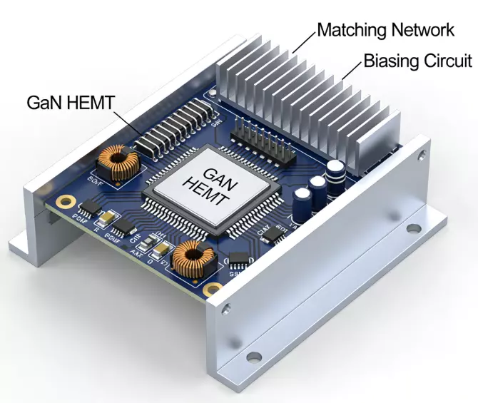
Selecting the appropriate RF transistor is pivotal for your DIY RF power amplifier’s success. Factors include operating frequency, power output, and efficiency needs. For low-power HF projects (1.8-54 MHz), the IRF510 MOSFET is popular due to its affordability and 50W capability, though it requires careful biasing to prevent oscillations.
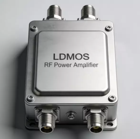
For higher power RF power amplifier, consider LDMOS transistors like the MRF300, which handle up to 300W but demand robust cooling. Key specs to evaluate:
- Gain (dB): Higher gain reduces stages needed.
- Frequency Range: Ensure fT (transition frequency) exceeds your band.
- Power Dissipation: Match to your supply voltage (e.g., 12-48V).
- Linearity: For SSB modes, choose devices with low intermodulation distortion.
Compare datasheets from manufacturers like NXP or Analog Devices. Test in a simple common-emitter RF power amplifier circuit to verify performance before full integration. Avoid overdriving—start at low power to tune.
Simple DIY RF Power Amplifier Circuit Example
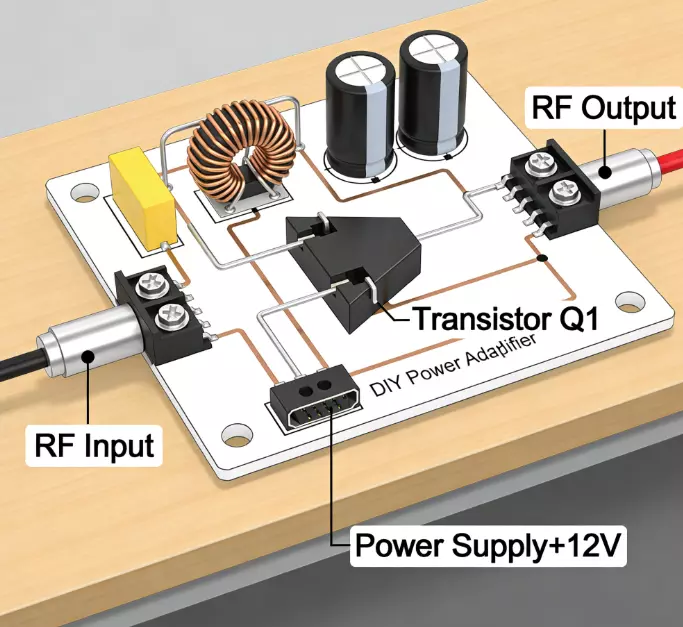
Let’s outline a basic 10W DIY RF power amplifier using an IRF510 MOSFET for 7-14 MHz operation. The schematic includes:
- Input: 50Ω matching network with a transformer (4:1 turns ratio) and capacitor for impedance transformation.
- Transistor Stage: IRF510 biased in Class AB with a 100Ω gate resistor for stability and a 10μH choke on the drain.
- Output: Pi-network filter (inductor and variable capacitors) tuned to suppress harmonics.
- Power Supply: 12V DC at 2A, with bypass capacitors.
Build on a copper-clad board: Solder the transistor to a heat sink first, then add passives. Input a 1mW signal from a signal generator; expect 20-25 dB gain. Simulate in LTSpice to predict waveforms—drain voltage swings should peak at twice the supply without clipping.
This push-pull variant can scale to 50W by paralleling transistors, but add feedback for linearity.
RF Power Amplifier Classes for DIY Designs
RF power amplifier classes define conduction angles and trade-offs:
- Class A: 360° conduction; high linearity (low distortion) but 25-50% efficiency. Ideal for low-power DIY where fidelity matters.
- Class AB: 180-360°; balances linearity and efficiency (50-70%). Common in SSB amplifiers.
- Class B: 180°; higher efficiency (up to 78%) but more distortion; use push-pull to cancel harmonics.
- Class C: <180°; 70-90% efficiency for CW/FM, nonlinear for modulated signals.
- Switching Classes (D, E, F): >90% efficiency via on/off operation; require precise tuning for DIY.
For a DIY RF power amplifier, start with Class AB for versatility. Waveforms illustrate differences—Class A shows constant current, while Class C pulses.
How to Test a DIY RF Power Amplifier Safely
Testing demands caution to avoid damage or injury. Use a dummy load (50Ω resistor rated for your power) to absorb output. Steps:
- Power up without input; check bias currents (e.g., 100-250mA for IRF510).
- Apply low-level input (1-10mW) and measure output with a power meter.
- Monitor temperature—use thermal cameras or probes; shut down if >80°C.
- Check for oscillations with a spectrum analyzer; add damping if needed.
- Gradually increase power, ensuring VSWR <2:1.
Wear safety glasses, use insulated tools, and have a fire extinguisher handy. Test RF power amplifier in short bursts to prevent overheating.
Common Problems in DIY RF Amplifier Projects
DIY builds often face issues like:
- Oscillations: From poor grounding or layout; solve with ferrite beads or better shielding.
- Overheating: Inadequate sinks; add fans or reduce duty cycle.
- Impedance Mismatches: Cause reflections; use Smith charts for matching.
- Harmonic Distortion: From nonlinearity; add filters.
- Component Failure: Overvoltage spikes; incorporate protection circuits.
Debug with scopes and analyzers—start simple and isolate stages.
Tips for Improving DIY RF Amplifier Performance
Optimize with:
- Impedance Matching: Use stubs or networks for max transfer.
- Cooling Enhancements: Thermal vias and compounds.
- Bias Optimization: Adjust for best linearity/efficiency.
- Feedback Loops: Negative feedback reduces distortion.
- Simulation Tools: LTSpice for pre-build testing.
- Shielding: Enclose to minimize EMI.
Iterate based on measurements for gains up to 30 dB.
When to Use RF Power Amplifier Modules Instead of DIY
While DIY offers customization, pre-built RF power amplifier modules shine for reliability and speed. Use modules for complex bands (>1 GHz) or high power (>100W), where certification and thermal design are critical. DIY suits learning or low-cost prototypes, but modules reduce risks like oscillations. For demanding apps, consider professional options.
Conclusion
Building a DIY RF power amplifier is rewarding, blending theory with hands-on skills. From understanding classes to safe testing, this guide equips you for success. For those seeking robust solutions, RF power amplifier manufacturer like ZR Hi-Tech offer high-quality RF power amplifiers tailored to professional needs. Always prioritize safety and iterate—happy building! Or just contact us!